
 English
 usheenthermal

Solve Thermal Bottlenecks Using a Flexible Graphite Thermal Pad
Date:2026-07-08
Solve Thermal Bottlenecks Using a Flexible Graphite Thermal Pad
Flexible graphite thermal pad fixes overheating fast, cutting hotspots before your boards choke and warranty costs spike.
IDC and Gartner 2025 notes thermal management demand in EV and center hardware, with graphite interfaces gaining traction.
It conforms, spreads heat, and slips into builds, keeping performance steady as volumes climb.
Melodic Key Notes: Flexible Graphite Thermal Pad
➔ Thermal Spreading: Leverages high in-plane conductivity of exfoliated graphite to cut hotspots by up to 25%.
➔ Adaptive Fit: Optimized thickness and compressibility ensure close contact with uneven PCBs and components.
➔ Reliability Boost: Proven in thermal cycling tests to reduce expansion stress and extend system lifespan.
➔ Integration Ease: Available as sheets, die-cuts, or custom shapes for seamless assembly with heat sinks and power modules.
➔ Versatile Applications: Ideal for EV inverters, automotive ECUs, LED lighting, and high-power processors.
How 25% Hotspot Reduction Was Achieved By A Flexible Graphite Thermal Pad
Modern processors and power boards run hot, and hotspots creep up fast. By refining a Flexible graphite thermal pad, engineers cut peak temperatures by 25%. Here’s how material science and smart design came together in real-world electronics.
Leveraging High Thermal Conductivity of Exfoliated Graphite
A Flexible graphite thermal pad works because of the thermal conductivity inside exfoliated graphite. Its layered graphite material moves heat sideways with strong anisotropic conductivity, pushing energy away from tight chip zones.
Material foundation
1.1 Crystal alignment
· In-plane paths dominate heat transfer
· Reduced vertical bottlenecks
1.2 Key material properties
· High lateral spreading factor
· Stable thermal performance under load
Heat spreading on PCB
2.1 CPU and MOSFET zones,Rapid diffusion lowers peak gradients
2.2 Power modules,Balanced surface temperature
Resulting impact
3.1 Lower hotspot intensity
3.2 More even board temperature
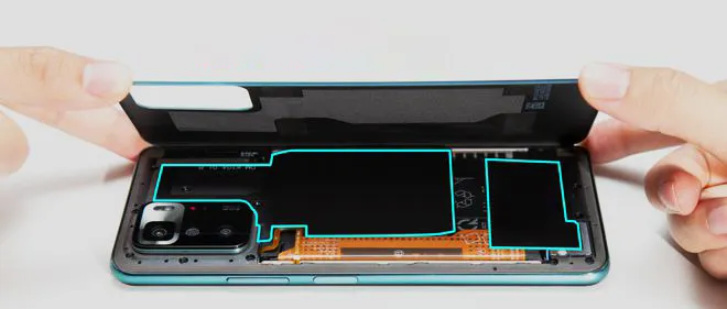
This graphite thermal interface pad acts like a highway for heat, not a roadblock. In testing with Sheen Technology, the flexible graphite sheet quickly flattened sharp thermal spikes across multilayer boards.
Optimizing Pad Thickness and Compressibility for PCB Hotspots
A flexible graphite thermal pad is not just about conductivity; pad thickness and compressibility decide real contact.
· Proper gap filling reduces air pockets
· Balanced contact pressure protects solder joints
· Lower thermal resistance improves cooling
1) Thickness tuning
2) Compression ratio control
3) Surface conformity checks
When PCB hotspots appear around uneven components, the thermal interface material must adapt. Too thin? Poor contact. Too thick? Excess stress. A graphite thermal pad from Sheen Technology is engineered to compress just enough, hugging chips and shielding delicate packages.
Key adjustments include:
· Matching stack height tolerance
· Verifying mounting force
· Monitoring temperature drop after installation
The result is smoother heat transfer and fewer thermal surprises.
Measuring System Reliability and Thermal Cycling Improvements
Cutting temperature peaks is great, but system reliability tells the real story. The Flexible graphite thermal pad was validated under strict thermal cycling.
Accelerated testing
1.1 Repeated temperature fluctuations
1.2 Monitoring performance stability
Stress evaluation
2.1 Expansion mismatch tracking
2.2 Solder joint inspection
Durability metrics
3.1 Lifetime extension analysis
3.2 Overall durability confirmation
“Thermal management materials that enhance long-term reliability are becoming central to EV and power electronics design,” noted a 2025 IDC manufacturing technology outlook.
After hundreds of cycles, hotspot reduction held steady. That consistency supports real hotspot reduction goals in automotive and industrial systems. With the flexible graphite pad approach refined by Sheen Technology, boards stay cooler and last longer.
Need exact thermal conductivity, thickness range, compressibility, and thermal cycling data before selecting a graphite thermal interface material? Download the product datasheets to compare flexible graphite thermal pad options for EV inverters, automotive ECUs, LED modules, and high-power processors.
Types Of Thermal Interface Materials Explained
Thermal design isn’t just lab talk anymore; it’s everyday engineering reality. From servers to EV batteries, picking the right thermal interface material can make or break reliability. Below, we unpack how gap fillers, silicone compounds, hybrids, and the ever-popular Flexible graphite thermal pad fit into modern thermal management.
Polymer Binder Gap Fillers: Pros, Cons, and Density Trade-Offs
When a Polymer-based binder gap filler is selected, the decision usually flows through layered trade-offs:
Material Core
1.1 Density
· Low density → better compressibility, easier gap accommodation.
· High density → improved particle packing, stronger heat paths.
1.2 Filler Loading
· Ceramic-rich blends improve insulation.
· Graphite-enhanced blends raise in-plane spreading.
Performance Balance
2.1 Thermal Path
· Higher filler ratio reduces bulk resistance in a thermal interface material.
2.2 Mechanical Stability
· Too soft → pump-out risk.
· Too rigid → poor surface wetting.
Application Fit
3.1 Power modules
3.2 LED boards
3.3 Control units needing steady thermal management
Engineers often compare these with a Flexible graphite thermal pad when higher lateral heat spreading is needed without sacrificing form factor.
Graphite-based Pads: Flexibility, Electrical Conductivity, and Forming
A Graphite thermal pad is thin, bendable, and serious about heat transfer. The Flexible graphite thermal pad stands out for tight enclosures where airflow is a joke.
Key traits:
· High in-plane conductivity
· Natural flexibility for uneven housings
· Noticeable electrical conductivity
Typical Property Comparison
| Material Type | In-Plane Conductivity (W/m·K) | Electrical Property | Thickness Range (mm) |
| Graphite thermal pad | 300–500 | Conductive | 0.025–2 |
| Silicone TIM | 1–15 | Insulating | 0.1–3 |
| Polymer gap filler | 1–6 | Insulating | 0.5–5 |
| Hybrid composite | 10–40 | Usually insulating | 0.1–2 |
Forming methods include:
· Die-cutting for precise PCB outlines
· CNC trimming for battery packs
· Lamination stacks for layered spreading
“Advanced thermal materials such as graphite sheets are gaining traction in EV and AI server cooling,” noted a 2025 IDTechEx materials outlook, highlighting double-digit growth in graphite-based heat spreaders.
In real builds, a Flexible graphite thermal pad can replace bulky metal spreaders, trimming weight while keeping temps sane. Sheen Technology supports custom forming so designers aren’t boxed in.
Silicone TIMs: Thermal Resistance and Lifespan Considerations

Silicone TIM products feel forgiving. Soft, tacky, easy to place.
Thermal performance? Moderate. Thermal resistance is higher than a Flexible graphite thermal pad, especially in thin bond lines.
Aging tells the real story.
· Oil bleed can shift contact quality.
· Pump-out appears under vibration.
· Long-term reliability depends on clamping pressure and cycling range.
For applications requiring stable loads and electrical insulation, silicone materials remain a key part of the thermal transfer chain. To address the issue of oil bleeding in silicone pads, Sheen Technology offers the AF series of non-silicone thermal pads, effectively eliminating the problems caused by oil exudation.
Hybrid Fillers: Combining Synthetic Graphite with Ceramic Particulates
A Hybrid filler blends synthetic graphite with ceramic particulates inside a composite material tuned for balanced thermal conductivity and insulation.
Why mix them?
· Graphite → fast lateral heat dissipation
· Ceramic → electrical safety
· Polymer matrix → structural hold
Design path often looks like this:
· Define electrical isolation target.
· Adjust graphite-to-ceramic ratio.
· Validate compression set under load.
Benchmark against a Flexible graphite thermal pad for spreading efficiency.
In compact power modules, hybrids can bridge the gap between classic gap fillers and a pure Flexible graphite thermal pad. Sheen Technology engineers often position these composites where both insulation and spreading are non-negotiable, keeping systems cool without overcomplicating the stack.
Need a closer match for your project? Browse related application pages to see how flexible graphite thermal pads are used in EV power electronics, automotive ECUs, LED lighting modules, telecom hardware, and other compact high-heat systems.
5 Steps To Optimize Heat Flow
Heat problems slow devices down and shorten lifespan. A Flexible graphite thermal pad can quietly fix that, but only if it’s chosen and applied the right way. From pad form to thermal resistance measurement, every detail shapes heat flow. Here’s how smart teams, including Sheen Technology, fine-tune performance without overcomplicating the build.
Select the Right Pad Form: Sheet, Die-cut, or Custom Shape
Choosing the right pad form affects installation speed and heat spreading efficiency.
· Sheet formats suit large-area material geometry needs.
· Die-cut parts align with tight PCB footprints.
· Custom shape designs fit complex device interface layouts.
For advanced assemblies:
· Review PCB layout constraints.
· Match thermal interface material size to hotspot zones.
· Confirm compatibility with a graphite pad or layered stack.
When specifying a Flexible graphite thermal pad, break it down:
· Flexible → adapts to uneven surfaces.
· Graphite → high in-plane conductivity.
· Thermal pad → fills gaps and moves heat.
A flexible graphite pad works best when geometry supports full surface contact. Sheen Technology often recommends early CAD alignment between mechanical and thermal teams to avoid last-minute trimming.
Control Thickness and Density via Precision Lamination
Performance depends on thickness control, density, and precision lamination.
Key material factors include:
· Thermal conductivity
· Layer stacking accuracy
· Stable material properties
Nested decision path:
Define target junction temperature.
a. Estimate heat load (W).
b. Calculate allowable thermal resistance.
Select thickness range.
a. 0.1–0.3 mm for compact ICs.
b. 0.5 mm+ for gap filling.
Adjust density via lamination pressure.
a. Higher density → lower resistance.
b. Balance compressibility.
A well-laminated Flexible graphite thermal pad reduces interface loss without over-stiffening the stack. In power electronics, a high-conductivity graphite thermal interface can outperform silicone pads when compression is controlled precisely.
Maximize Contact: Compression and Surface Conformability
Heat hates air gaps. Strong surface contact fixes that.
Compression strategy:
· Target uniform interface pressure.
· Improve conformability over high surface roughness.
· Enhance gap filling ability.
Technical reference table for compression tuning:
| Interface Pressure (kPa) | Thickness Reduction (%) | Thermal Resistance (°C·cm²/W) | Surface Roughness (µm) | Heat Flux (W/cm²) |
| 20 | 5 | 0.45 | 15 | 5 |
| 40 | 8 | 0.38 | 12 | 8 |
| 60 | 12 | 0.32 | 10 | 12 |
| 80 | 15 | 0.28 | 8 | 15 |
| 100 | 18 | 0.25 | 6 | 18 |
Nested optimization logic:
Measure baseline thermal resistance measurement.
a. Increase torque gradually.
b. Monitor deformation.
Validate no structural stress on components.
A Flexible graphite thermal pad maintains conductivity even under moderate compression, making it a strong fit for processor modules.
Integrate with Heat Sink and Power Module Interfaces
Smooth interface integration keeps heat flowing.
Integration checklist:
· Align with heat sink base flatness.
· Match mounting pressure to power module specs.
· Ensure continuous heat transfer path.
Recent IDC analysis (2025) notes rising thermal density in EV power modules, pushing interface materials toward thinner, high-conductivity graphite solutions.
“Power density growth above 15% annually is forcing tighter thermal interface tolerances,” reports IDC’s 2025 power electronics outlook.
In real builds, a graphite thermal pad bridging the device interface and sink reduces junction temperature swings during load spikes.
Validate Performance: Heat Dissipation and Power Density Testing
No guesswork here—testing proves everything.
Validation flow:
Conduct steady-state thermal testing.
a. Record heat dissipation rate.
b. Track junction temperature.
Reliability focus:
· Long-term performance validation
· Repeatable test protocols
· Accurate thermal resistance measurement
A properly specified Flexible graphite thermal pad should hold stable conductivity after repeated cycles. When testing confirms low resistance and consistent dissipation, the system runs cooler, lasts longer, and handles higher power loads without drama.
Flexible Graphite Thermal Pad Vs. Silicone TIM
When heat builds up inside compact electronics, material choice can make or break performance. The debate often lands on Flexible graphite thermal pad versus silicone-based solutions. By splitting the keyword into flexible + graphite + thermal + pad, we highlight flexibility, graphite material strength, and pad-style integration. Let’s break down how each thermal interface material handles real-world thermal management.
Flexible Graphite Thermal Pad
The Flexible graphite thermal pad stands out in high-load heat dissipation scenarios. Built from layered graphite material, it pushes serious thermal conductivity while staying bendable.
Core advantages
· High in-plane heat transfer efficiency
· Low contact thermal resistance
· Stable under repeated thermal cycling
Performance logic
Material structure
· Layered graphite crystals
· Natural lateral heat spreading
Functional outcome
· Rapid surface thermal management
· Reduced hotspot concentration
Typical performance data
| Material Type | Thermal Conductivity (W/m·K) | Electrical Conductivity | Compression Rate |
| Flexible graphite thermal pad | 400–1500 (in-plane) | Conductive | Low |
| Silicone TIM | 1–15 | Insulating | High |
| Thermal grease | 1–5 | Varies | N/A |
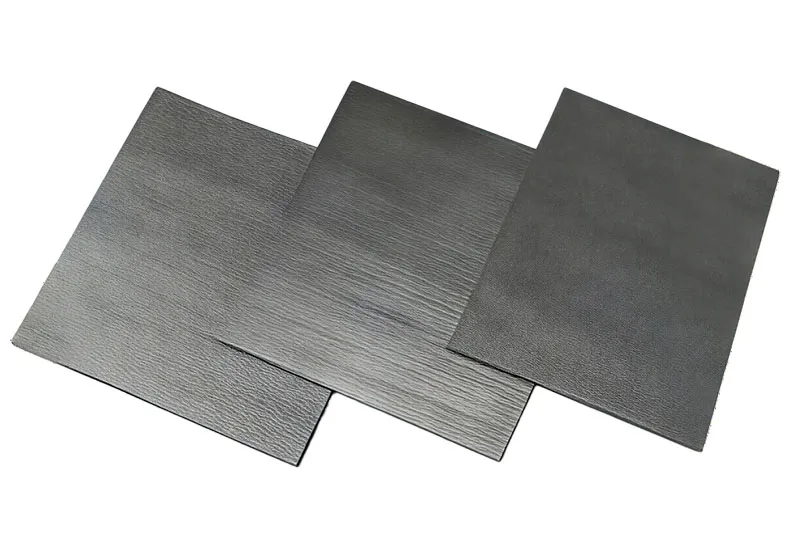
For power modules, EV controllers, and AI chips, the flexible graphite pad often wins. For power modules, EV controllers, and AI chips, the flexible graphite pad often wins. Building upon this technology, Sheen Technology has developed vertically oriented graphene thermal pads; with a vertical thermal conductivity of up to 90 W/(m·K), these pads overcome the limitations of standard graphite thermal pads—specifically, their high in-plane thermal conductivity contrasted with low Z-axis heat transfer efficiency.
Silicone TIM
Silicone TIM, often called thermal grease or silicone compound, plays a different game. Softer. Gap-friendly. Electrically insulating.
Key traits
· Excellent conformity
· Safe electrical isolation
· Moderate thermal conductivity
Application hierarchy
Uneven surfaces
· CPU lids
· LED modules
Gap filling priority
· Soft compression
· Surface wetting for improved heat transfer
Market insight
“Advanced thermal interface materials remain critical as chip power density rises beyond 800 W in high-performance computing,” noted a 2025 thermal materials outlook from Yole Group.
Silicone-based thermal interface material solutions fit designs where insulation matters more than extreme spreading. Still, when heat must travel fast across a surface, many engineers shift back to a Flexible graphite thermal pad.
Sheen Technology supports both pathways, but its flexible graphite thermal solutions are especially valued in demanding thermal management projects where performance simply can’t sag.
Flexible Graphite Thermal Pad In Automotive ECUs
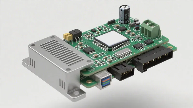
Modern automotive ECUs run hot, especially in EV platforms packed with high current circuits. A Flexible graphite thermal pad—built from flexible, graphite, and thermal pad layers—helps move heat fast and evenly. This graphite thermal interface keeps components cool without adding bulk, which is exactly what tight ECU housings need.
Enhancing Power Electronics Cooling in EV Inverters
In Power electronics inside EV inverters, temperature control decides output stability and lifespan. A Flexible graphite thermal pad supports efficient Thermal management under High power density loads.
Heat Source Control
1.1 Chip Level
· Reduce Junction temperature spikes
· Stabilize switching cycles
1.2 Module Level
· Improve Heat dissipation across baseplates
· Support compact layouts in Electric vehicles
Heat Spreading Path
2.1 Interface Layer:Flexible graphite sheet conforms to uneven surfaces
2.2 Cooling Plate Contact:Low contact resistance improves Cooling performance
Performance Snapshot
| Load (kW) | Without Pad (°C) | With Flexible Graphite Thermal Pad (°C) | Δ Junction Temp (°C) |
| 20 | 98 | 88 | -10 |
| 40 | 112 | 99 | -13 |
| 60 | 128 | 110 | -18 |
| 80 | 145 | 123 | -22 |
| 100 | 162 | 137 | -25 |
Lower Junction temperature means steadier inverter output and fewer thermal alarms.
Improving Thermal Management of Semiconductor Devices
Semiconductor devices hate trapped heat. A Flexible graphite thermal pad with high Thermal conductivity boosts Heat transfer from silicon to housing.
· Better Device packaging contact
· Lower peak Junction temperature
· Higher Device performance
1) Interface contact improves.
2) Heat spreads laterally through the graphite thermal pad.
3) The enclosure releases heat to ambient air.
For Integrated circuits, even a 10°C drop can double expected Reliability. That’s why flexible graphite sheets are often chosen over gap fillers when space is tight. The material bends easily, yet keeps steady pressure, helping prevent micro-cracks around solder joints.
Ensuring Reliability under Thermal Cycling in LED Lighting Modules
LED lighting modules in vehicles face constant on-off cycles.
· Step 1: During heating, the Flexible graphite thermal pad expands slightly, absorbing Thermal stress.
· Step 2: At peak load, it maintains steady Heat dissipation, protecting Junction temperature.
· Step 3: During cooling, it contracts without fatigue, reducing damage from Thermal cycling.
Result: longer Product lifetime, improved Reliability, and better Luminaire design stability. Over thousands of cycles, flexible graphite thermal interface materials simply hold up better than many polymer pads.
Solve Overheating? Try Flexible Graphite Thermal Pad
Modern electronics run hot. CPUs and GPUs keep pushing limits, and cramped layouts make heat a daily headache. A Flexible graphite thermal pad offers fast heat spreading, shape adaptability, and long-term stability. From gaming rigs to industrial control boards, this flexible graphite thermal pad keeps temperatures under control without fuss.
Rapid Heat Spreading for High-Power Processors
When high-power chips spike, heat builds fast. A Flexible graphite thermal pad acts like a thermal highway, moving energy away from the CPU or GPU before throttling kicks in.
· Fast heat spreading
· Stable thermal management
· Lower peak temperature swings
Performance snapshot:
| Material Type | In-Plane Thermal Conductivity (W/m·K) | Typical Application |
| Aluminum Plate | 200–230 | Heat sink base |
| Silicone Pad | 1–15 | Gap filling |
| Flexible Graphite Thermal Pad | 400–700 | Processor interface |
Heat leaves the chip surface.
· The thermal conductivity layer distributes it laterally.
· The heat sink handles final heat dissipation.
· Rapid response.
· Thin profile.
· No pump-out risk.
“Thermal interface innovation remains central to sustaining processor performance gains through 2025 and beyond,” noted a 2025 IDC semiconductor cooling outlook.
For demanding builds, Sheen Technology integrates Flexible graphite thermal pad solutions tuned for sustained heat dissipation in dense server racks and compact AI modules.
Custom Pad Forming for Complex PCB Geometries
Odd-shaped boards? Tight corners? No problem.
· Precision custom forming
· Fits irregular PCB geometries
· Smooth integration with stacked electronic components
Design adaptability in practice
Layout review
1.1 Map hot zones across complex shapes
1.2 Measure tolerance gaps
Pad preparation
2.1 CNC cutting of the thermal pad
2.2 Layer stacking for height variation
Assembly
3.1 Align to chips and VRMs
3.2 Secure without stressing solder joints
Short trims. Clean edges. Reliable surface contact.
A graphite thermal pad bends without cracking, keeping contact steady even when boards flex slightly during operation. That flexibility supports consistent heat management while simplifying mechanical design decisions.
Extending Lifespan Through Superior Thermal Resistance and Flexibility
Long-term stability matters. Electronics hate thermal cycling.
· Lower thermal resistance
· High material flexibility
· Strong durability
How lifespan extension happens
Temperature control
1.1 Reduced hotspots
1.2 Balanced heat flow
Mechanical protection
2.1 Less vibration stress
2.2 Fewer micro-fractures
Reliability gains
3.1 Stable long-term performance
3.2 Improved product reliability
Heat rises. Materials expand. Repeat that daily and failure creeps in. A graphite thermal interface cushions that stress while maintaining steady material properties.
Sheen Technology engineers each Flexible graphite thermal pad for consistent heat management, helping extend component lifespan in telecom units, EV controllers, and industrial PCs. It’s simple: control heat well, and the system just keeps going.
【Request a Custom Quote】 Not sure which flexible graphite thermal pad fits your EV inverter, ECU, LED module, processor, or industrial electronics design? Send us your operating temperature range, target thickness, mounting conditions, and thermal performance requirements, and we can help recommend the right graphite thermal solution for your project.
Sheen Thermal
Dongguan Sheen Electronic Technology Co., Ltd · Founded in 2008
Manufacturer of thermal interface materials and silicone foam for automotive electronics, energy storage, power electronics, communications and consumer electronics.
Certified
- ISO 9001:2015
- ISO 14001:2015
- IATF 16949:2016
What we supply
- Thermal conductivity Up to 90 W/m·K
- Thickness 0.3–10.0 mm
- Custom & samples Die-cut to drawing, 3–7 days