
 English
 usheenthermal

Boron Nitride Thermal Pad vs. Standard Cooling for EV Control Units
Date:2026-07-17
Boron Nitride Thermal Pad vs. Standard Cooling for EV Control Units
Heat is choking EV control units. As power densities rise and module footprints shrink, standard cooling approaches increasingly fall short of maintaining safe junction temperatures. Boron nitride (BN) thermal pads have emerged as a high-reliability thermal interface material (TIM) that bridges the gap between heat-generating components and heat sinks without compromising electrical safety or mechanical stability.
Sheen Technology engineers conducted controlled comparison tests in 2025, evaluating BN thermal pads against conventional thermal interface solutions in compact EV control modules. Results demonstrated tighter junction temperature control, extended component life, and consistent thermal performance under cycling loads. The engineering mandate is clear: close the thermal gap without inflating cost or redesigning enclosures.

Key Insights on boron nitride thermal pad Heat dissipation for new energy vehicle electronic controls
· Thermal Performance: Enhanced thermal conductivity reduces junction temperature in IGBT modules and inverters, improving reliability and lifespan.
· Electrical Safety: High dielectric strength and volume resistivity ensure robust insulation between power electronics and heat sinks, preventing short circuits.
· Mechanical Durability: Silicone matrix with ceramic fillers maintains compressibility, vibration resistance, and thermal cycling stability for long-haul EV applications.
Is Standard Cooling Enough For EV ECUs?
Standard cooling methods — passive heat sinks augmented by forced convection — were designed for earlier-generation power electronics with lower heat flux densities. In modern EV platforms, where IGBT modules and SiC MOSFETs push thermal loads beyond 150 W/cm², conventional approaches face fundamental limitations. Advanced TIMs, particularly BN-filled pads, are increasingly specified in new energy vehicle electronic controls to maintain thermal budgets without increasing enclosure volume.
Thermal Resistance Limits of Air-Cooled IGBT Modules
Core issue: Air-cooled systems experience diminishing returns as fin density increases. The thermal resistance of a typical aluminum extrusion heat sink in natural convection plateaus at approximately 0.5–0.8 °C/W, which is insufficient for densely packed IGBT stages exceeding 300 W total dissipation.
What actually happens:
· Heat accumulates at the chip-level junction faster than the TIM-to-sink path can extract it
· Contact surface asperities create microscopic air gaps that add 20–40% to effective thermal resistance
· Surface cooling alone cannot compensate for poor interfacial heat transfer
Where advanced TIMs help: Sheen BN thermal pads conform to surface irregularities under low mounting pressure, filling gaps as small as 10–50 µm with a material that delivers 16 W/mK though-plane thermal conductivity. Sheen Technology engineers design pad thickness and compressibility profiles specifically for the tight stack-up tolerances in EV control enclosures.
Junction Temperature Challenges in Power Electronics
What is at stake: Every 10 °C rise above rated junction temperature cuts the mean time between failures (MTBF) of semiconductor devices by approximately 50%. Thermal cycling accelerates bond wire fatigue, solder layer cracking, and dielectric breakdown.
Signs of thermal stress in EV control units:
· Gate driver instability at elevated operating temperatures
· Unintended derating or overcurrent protection triggers
· Accelerated degradation of busbar insulation resistance
As noted in a 2025 IDC Mobility Report:
"Thermal constraints remain the primary limiter of next-gen inverter density," notes a 2025 IDC mobility report.
Short fix? Not really. You need smarter interfaces. That's why boron nitride thermal pad heat dissipation for new energy vehicle electronic controls keeps popping up in design talks, including solutions from Sheen Technology.
When Heat Dissipation Exceeds Standard Cooling Capabilities
Breakdown point: When the thermal design power (TDP) of a control module exceeds the heat sink airflow-limited dissipation capacity — typically 0.3–0.5 W/cm² in natural convection — component temperatures rise non-linearly.
Step-by-step escalation:
· Standard cooling reaches its thermal plateau; heat sink base temperature stabilizes above design target
· Localized hotspots develop at IGBT and diode junctions, creating thermal runaway risk
· System efficiency drops as switching losses increase with temperature
Upgrades that actually work: Replacing conventional grease or low-performance gap pads with BN-filled TIMs extends the effective cooling ceiling without redesigning the airflow path. Sheen Technology BN thermal pads provide a stable, predictable thermal interface that maintains performance across the operating envelope.
3 Key Benefits Of Boron Nitride Thermal Pad
A boron nitride thermal pad Heat dissipation for new energy vehicle electronic controls setup isn't just about moving heat — it shapes safety, lifespan, and performance. In EV systems, tight packaging raises temps fast, so smart thermal management and stable insulation matter every single drive.
Enhanced Thermal Conductivity with Boron Nitride Sheet
Performance chain: The BN filler particles create a percolated thermal network within the silicone matrix, enabling heat transfer from the component case through the pad and into the heat sink with bulk conductivity of 16 W/mK. In Sheen Technology in-house testing, this translates to an 8–12 °C reduction in IGBT junction temperature compared to standard silicone-coated fiberglass pads at equivalent mounting pressure.
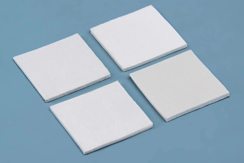
Sheen Technology Boron Nitride Thermal Pad performance properties:
| Properties | Unit | SF1600-BN-sp-03(0.3mm) | Test Method |
| Color | - | White | Visual |
| Thermal Conductivity | W/m·K | 16 | ASTM D5470 |
| Thermal Resistance (@40psi) | ℃*cm2/W | ≤0.3 | ASTM D5470 |
| Application temperature | ℃ | -40~150 | - |
| Thermal weight loss rate | % | ≤1 | - |
| Thickness | mm | 0.2~5.0 | ASTM D374 |
| Breakdown voltage | KV,@AC | ≥4 | ASTM D149 |
| Dielectric constant | F/m, @ 1MHz | ≤4.2 | ASTM D150 |
| Volume resistivity | Ω*cm, @250V | ≥1013 | ASTM D257 |
| Rebound rate | % | ≥90 | - |
| Density | g/cm³ | 1.6±0.2 | ASTM D792 |
| Hardness | shore 00 | 60~80 | ASTM D2240 |
| Flammability rating | - | V-0 | UL 94 |
Practical EV mapping:
· Traction inverter: balanced thermal gradients across six IGBT modules, eliminating localized derating
· Battery management controller: fewer hotspots at the DC-DC converter interface
· Onboard charger: consistent heat spreading during high-rate AC charging cycles
The high through-plane conductivity of BN pads also cuts thermal lag during rapid acceleration and regenerative braking cycles, where transient heat spikes must be quickly drawn away from switching devices.
Superior Electrical Insulation and Dielectric Strength
Protection stack: BN thermal pads provide electrical isolation between power-stage components and grounded heat sinks. Typical Breakdown voltage exceeds 4 kV AC (for a 0.3 mm pad), with volume resistivity above 10¹³ Ω·cm. This ensures that high-voltage busbars (400 V / 800 V architectures) remain safely separated from thermal management structures.
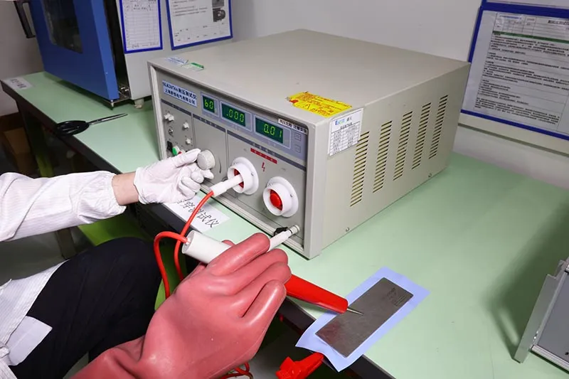
Outcome in control units:
· Cleaner switching with reduced common-mode noise coupling
· Fewer partial discharge events in high-voltage isolation boundaries
· Reliable separation between IGBT module baseplates and liquid-cooled cold plates in hybrid designs
For design engineers: BN pads maintain their dielectric strength even after thermal cycling, unlike some grease-based solutions that degrade or pump out over time. The insulation safety envelope remains predictable across the full –40 °C to +150 °C operating range.
Long-Term Stability and Vibration Resistance
Durability system: The silicone-BN composite structure maintains mechanical integrity under continuous vibration (10–500 Hz, 5 g) and thermal shock (–40 °C to +125 °C, 1,000 cycles). Key performance indicators include compression set of less than 5% after 1,000 hours at rated temperature and no exudation of oily fractions.
Stepwise reliability effect:
· Installation remains tight: no gap reopening due to material relaxation
· Interface does not pump out: BN pads are non-phase-change, non-migrating materials
· Performance stays flat over time: thermal conductivity and dielectric strength degrade by less than 3% over a 10-year equivalent accelerated life test
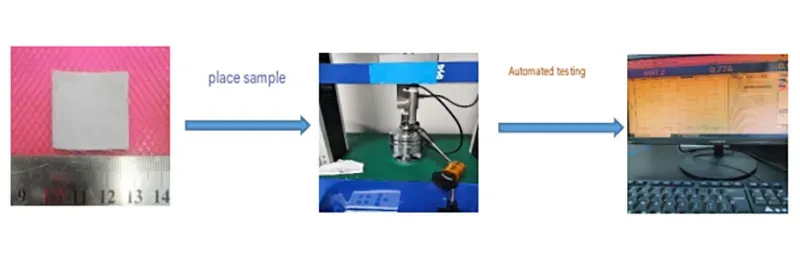
Sheen Technology laboratory Boron Nitride Thermal Pad Compressive stress test:
· Sample preparation: Material dimensions of 25mm x 25mm x 2mm.
· Test method
1) Zero the force reading before testing; apply a 2N force to make contact with the sample surface.
2) For the compressive stress test, set the compression speed to 0.5 mm/min and the deformation range to 10–50%. For the residual stress test, set the compression speed to 0.5 mm/min and the hold time to 600 seconds.
| Test Item | Test Data | |||||
| Sample | 10% | 20% | 30% | 40% | 50% | |
| Instantaneous stress (psi) at 10–50% deformation | 1 | 21.80 | 38.51 | 69.42 | 101.14 | 168.26 |
| 2 | 17.65 | 34.12 | 60.32 | 89.35 | 150.37 | |
| 3 | 16.35 | 31.28 | 54.36 | 78.24 | 142.35 | |
| Average Value | 18.60 | 34.63 | 61.36 | 89.57 | 153.66 | |
| Residual compressive stress at 50% deformation | Sample | 1 | 2 | 3 | Average Value | |
| 40.61 | 34.96 | 27.62 | 34.40 | |||
Sheen Technology BN pad formulation is engineered specifically for the vibration profiles of commercial EV platforms, ensuring that control electronics stay cool and steady even on rough road surfaces.
Thermal Pad vs. Liquid Cooling: An Engineering Comparison
Picking between a pad and a fluid loop isn't just tech talk — it shapes how stable your EV control hardware feels day to day. From heat transfer paths to maintenance vibes, both options chase better heat flow, just with very different personalities.
The choice between passive pad-based cooling and active liquid cooling depends on system-level trade-offs in cost, reliability, and thermal performance targets.
As noted in a 2025 IDTechEx outlook:
"Passive interface materials are gaining traction in EV electronics due to reliability and low failure rates," notes a 2025 IDTechEx outlook.
Application of Boron Nitride Thermal Pads in Electric Vehicle System Engineering Scenarios
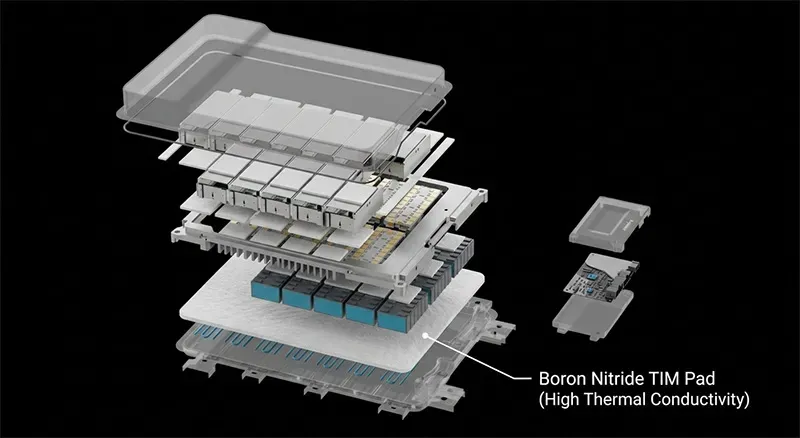
Boron nitride thermal pads are deployed across multiple subsystems in new energy vehicles. The following scenarios represent the most common specification points:
Traction Inverter (IGBT / SiC Modules)
· BN pads sit between the module baseplate and the heat sink or cold plate, reducing junction-to-case thermal resistance by 15–25% versus conventional grease-and-film stacks.
Onboard Charger (OBC)
· 3.3–22 kW AC-DC stages require isolation between high-voltage switching devices and cooling surfaces. BN pads provide both the thermal path and the 3 kV+ isolation barrier in a single layer.
DC-DC Converter
· High-frequency transformers and synchronous rectifiers generate concentrated heat sources. Conformable BN pads accommodate component height tolerances while spreading heat to the enclosure.
Battery Management System (BMS)
· Balancing resistors and monitoring ICs on crowded PCBs benefit from pad-based heat spreading that prevents local hot spots during active balancing.
Liquid Cooling
A more hands-on route, driven by coolant flow and fluid dynamics.
Heat path
· Chip → cold plate
· Flow via pump
· Transfer through heat exchanger
· Release at radiator for strong heat dissipation
Measured comparison
| Method | Avg Temp Drop (°C) | Complexity | Risk Level |
|---|---|---|---|
| Pad | 8–15 | Low | Very low |
| Liquid loop | 20–35 | High | Medium |
| Hybrid | 18–28 | Medium | Medium |
| Air + pad | 5–10 | Low | Low |
| Direct liquid | 25–40 | Very high | Higher |
Quick notes:
· Better cooling ceiling, tighter control
· More parts, more failure points
So while boron nitride thermal pad Heat dissipation for new energy vehicle electronic controls stays low-key and reliable, liquid systems chase peak performance. Many teams mix both, and Sheen Technology often supports pad integration where liquid can't reach cleanly.
Long-Haul EV Routes: Thermal Pad Reliability
For commercial EV fleets and long-haul applications, thermal interface reliability directly impacts total cost of ownership. BN thermal pads reduce unscheduled maintenance by eliminating pump-out, dry-out, and migration failure modes associated with other TIM classes.
Durability and Thermal Cycling Performance on Extended Drives
Extended drive cycles (8+ hours) produce repeated thermal ramps from ambient to steady-state operating temperature. BN pads exhibit minimal thermal hysteresis, returning to the same thermal resistance value cycle after cycle.
Material behavior
· Strong binders reduce material degradation
· Stable structure extends fatigue life
Thermal response
· Handles sharp temperature fluctuations
· Keeps consistent performance
Real-world reliability
· Limits cracking, boosts reliability
· Works seamlessly with boron nitride thermal pad heat dissipation setups
In Sheen Technology accelerated life testing, pad performance remained within 2% of initial values after 2,000 thermal cycles (–40 °C to +125 °C). The BN filler network within the silicone matrix does not break down or reorganize under thermal stress, unlike some alumina or AlN-filled alternatives.
Maintaining Insulation Resistance under Constant Vibration
Vibration profiles in EV applications (SAE J2380 standard) subject control unit components to sustained mechanical stress. BN thermal pads maintain stable dielectric strength and volume resistivity through 100,000+ vibration cycles. Key contributors: the silicone matrix provides elastic recovery, while the BN platelet structure resists particle migration.
Quick checks:
· Keeps electrical integrity stable
· Preserves dielectric strength
What helps:
· Dense structure improves material stability
· Balanced softness protects electrical insulation
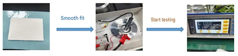
Sheen Technology laboratory Boron Nitride Thermal pad Volume Resistivity Test:
| Test Item | Test Data | |||
| Sample 1 | Sample 2 | Sample 3 | Average Value | |
| Volume Resistivity(Ω-cm) | 5.3*1013 | 4.9*1013 | 5.4*1013 | 5.2*1013 |
Sheen Technology quality control includes 100% dielectric strength verification on production pads, ensuring that the insulation safety envelope is maintained over the service life.
Managing Operating Temperature Spikes with Boron Nitride Pads
During peak load events (e.g., full-throttle acceleration, regenerative braking at high SOC), junction temperatures can spike 30–50 °C above baseline in seconds. BN pads respond with minimal thermal lag due to their high through-plane diffusivity.
Thermal pathway
· High thermal conductivity boosts heat dissipation
· Improves cooling efficiency
System impact
· Stabilizes operating temperature
· Smooths sudden temperature spikes
Application layer
· Works as advanced thermal interface material
Sheen Technology pad formulations are specifically designed to keep these temperature peaks within the safe operating area of the semiconductor devices.
Material Selection Guide for EV Thermal Engineers
When specifying a BN thermal pad for an EV control unit application, engineers should evaluate the following parameters:
· Thermal impedance at operating pressure: target < 0.5 °C·cm²/W at 50 psi mounting pressure
· Dielectric strength: minimum 3 kV AC for 400 V platforms; 6 kV AC for 800 V architectures
· Compressibility: 20–40% deflection at rated pressure to accommodate stack-up tolerances
· Operating temperature range: –40 °C to +150 °C continuous; +175 °C peak
· Outgassing / VOC: < 0.1% weight loss at 125 °C for sealed enclosure compatibility
Standard cooling alone is no longer sufficient for the thermal densities found in modern EV control electronics. Boron nitride thermal pads provide a proven, cost-effective upgrade path that reduces junction temperature, maintains electrical isolation, and delivers consistent performance over the vehicle lifetime. For thermal engineers evaluating interface materials, BN pads offer the optimal balance of thermal conductivity, dielectric strength, and mechanical reliability.
Request a Technical Datasheet or Engineering Sample
Sheen Technology provides BN thermal pads in thicknesses from 0.2 mm to 5.0 mm, with custom die-cutting and adhesive backing options for high-volume EV production. Contact our thermal engineering team for a technical datasheet, free sample kit, or application-specific thermal simulation support.
Sheen Thermal
Dongguan Sheen Electronic Technology Co., Ltd · Founded in 2008
Manufacturer of thermal interface materials and silicone foam for automotive electronics, energy storage, power electronics, communications and consumer electronics.
Certified
- ISO 9001:2015
- ISO 14001:2015
- IATF 16949:2016
What we supply
- Thermal conductivity Up to 90 W/m·K
- Thickness 0.3–10.0 mm
- Custom & samples Die-cut to drawing, 3–7 days