
 English
 usheenthermal

Optimizing High-Power-Density Inverter Thermal Management Systems
Date:2026-08-05
High-power-density inverter thermal management is where designs either shine or burn out fast; push more power into tighter spaces and heat stops being a side issue and starts calling the shots.
Hotspots creep in, interfaces bottleneck, insulation cracks, coolants slack off, and costs climb until failures hit. Smart material choices fix the chain reaction and keep performance, uptime, and budgets steady.
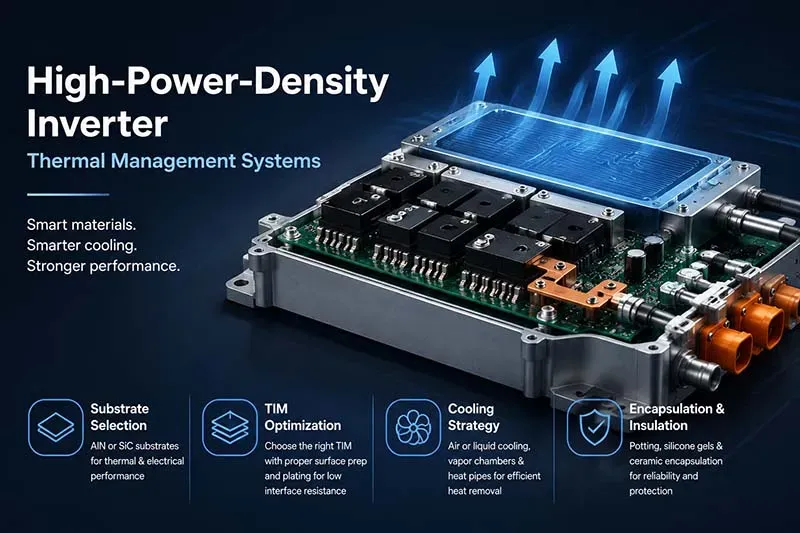
Reading Notes on High-power-density Inverter Thermal Management
➔ Substrate Selection: Opt for aluminum nitride or silicon carbide substrates to balance thermal conductivity with electrical insulation under extreme conditions.
➔ TIM Optimization: Compare greases, pads, phase-change materials, and liquid-metal TIMs; ensure proper surface prep and plating compatibility for minimal interface resistance.
➔ Cooling Strategy: Evaluate air vs. liquid cooling – use deionized water or glycol loops for compact high-flux designs, or vapor chambers and heat pipes for uniform heat spreading.
➔ Encapsulation & Insulation: Employ potting compounds, silicone gels, and ceramic encapsulation to protect against vibration, moisture, and voltage stress.
High-Power-Density Inverter Thermal Management Overview
High-power-density inverter thermal management keeps pushing limits as designs shrink and heat climbs. In real builds, balancing heat dissipation, insulation, and durability feels like tuning a stubborn engine—small tweaks, big consequences.
Thermal Challenges in Compact Power Stacks
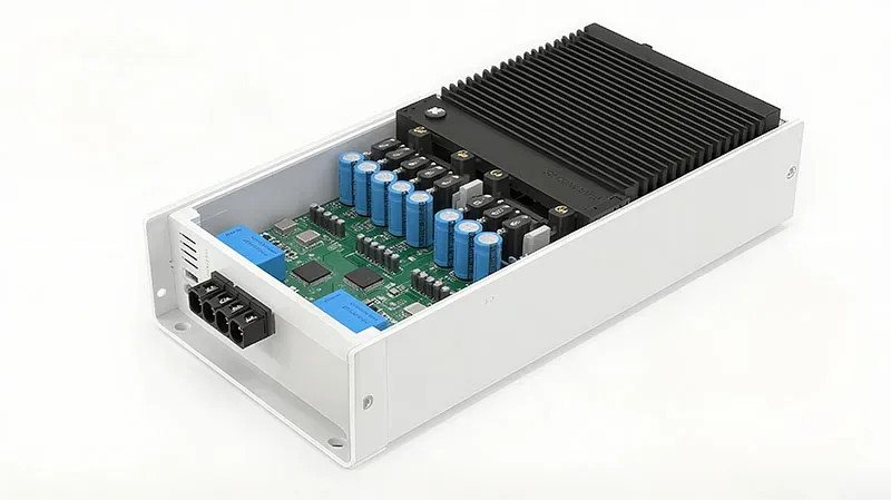
In compact design power stacks, heat doesn’t spread nicely—it clusters.
Core stress chain
- Source: rising power density in power electronics
- Effect: uneven thermal management paths
- Result: localized hot spots
Limited airflow
- Higher thermal resistance
- Faster material fatigue
Outcome layer
- Substrate strain
- Solder cracking
- Insulation wear
High-power-density inverter thermal management here means reducing peaks, not just averages. Sheen Technology often tackles this by tightening layout symmetry and shortening thermal paths.
Selecting Aluminum Nitride and Silicon Carbide Substrates
Start with material selection tied to load and switching frequency.
Match aluminum nitride where thermal conductivity and electrical insulation must coexist.
Shift to silicon carbide when voltage and temperature spike.
Integrate into power modules with compatible packaging to avoid mismatch stress.
High-power-density inverter thermal management benefits when substrates stop being passive and start acting like heat highways.
Thermal Interface Materials: From Grease to Liquid Metal TIMs
- Thermal interface materials fill micro-gaps; that’s the baseline.
- Thermal grease works, but pump-out can creep in over time.
- Phase change materials stabilize bond line thickness under cycling.
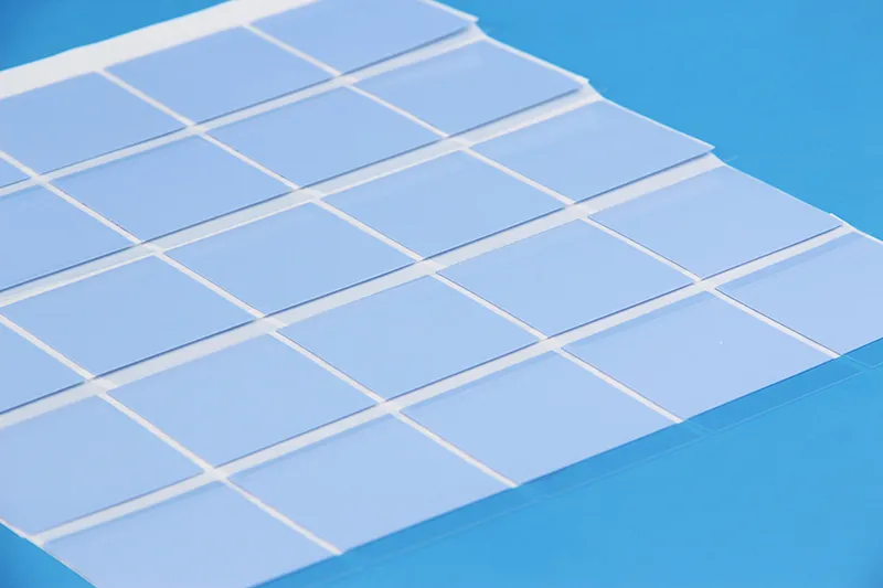
Then comes liquid metal—serious heat transfer, low thermal resistance, but picky about surfaces. Nickel plating isn’t optional here. High power density inverter thermal setups often mix TIM types across layers for control, not just conductivity.
Integrating Potting Compounds and Ceramic Encapsulation
Protection stack
- Potting compounds: Boost vibration resistance, Add moisture protection
- Silicone gels: Improve heat transfer buffering
Ceramic encapsulation
- High dielectric strength
- Stable thermal protection
Reliability loop
- Reduced micro-cracks
- Longer lifecycle
Sheen Technology applies this layered approach so high-power-density inverter thermal management stays stable even when environments get rough. Need exact thermal conductivity, dielectric strength, thermal resistance, insulation performance, and reliability data before selecting materials for your inverter design? Download the product datasheets to compare thermal pads, ceramic insulation sheets, thermal adhesives, and other high-performance thermal solutions for high-power-density inverter applications.
4 Common Thermal Management Mistakes
High-power-density inverter thermal management sounds fancy, but small oversights wreck performance fast. From paste misuse to fluid choices, these missteps quietly raise temps and kill efficiency in high power inverter thermal management setups.
Overreliance on Thermal Grease Without Proper Surface Prep
In High-power-density inverter thermal management, paste isn’t magic—it only works when the base is right.
Surface reality check
- Flatness: uneven plates increase contact resistance
- Cleanliness: dust traps air, forming interface voids
- Pressure: uneven mounting ruins heat transfer
What actually happens
- Excess thermal grease fills gaps poorly
- Reduced thermal conductivity at the interface
- Rising junction temps despite good thermal interface material
Quick fixes
- Lap surfaces lightly
- Use controlled spread, not blobs
- Verify clamp uniformity
This alone can make or break inverter thermal management.
Ignoring Vapor Chamber Materials in Heat Sink Design
Skipping vapor chamber tech in High-power-density inverter thermal management is like cooling with one hand tied.
Heat spreading chain
- Core: working fluid absorbs heat via phase change
- Transport: wick structure redistributes energy
- Output: uniform dissipation across heat spreader
Compare paths
- Solid heat sink design → localized hotspots
- Vapor chamber + copper → balanced thermal field
Short version: better thermal conductivity, fewer spikes, longer device life.
Underestimating Polyimide Film Insulation Limits
Polyimide film holds up well—until it doesn’t.
Stress factors
- High thermal limits + voltage cycling
- Declining dielectric strength
Failure path
- Micro degradation
- Reduced breakdown voltage
- Electrical leakage in inverter thermal management systems
Alternatives
- Ceramic layers
- Mica with stable material properties
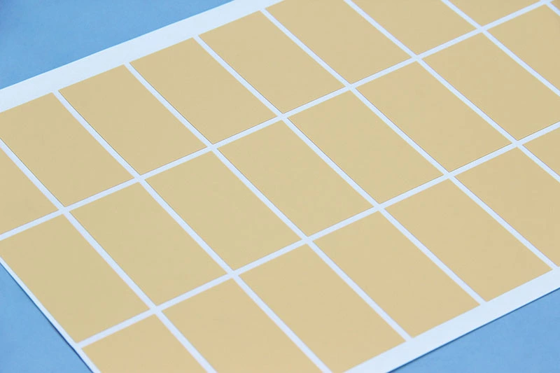
For thermal management for high power density inverters, insulation aging matters more than expected.
Using Mineral Oil Without Addressing Dielectric Fluid Properties
In High-power-density inverter thermal management, fluid choice isn’t casual.
Fluid behavior stack
Viscosity affects fluid circulation
- Thermal conductivity drives cooling rate
- Dielectric properties define safety margins
Mineral oil limits
- Lower breakdown voltage over time
- Oxidation reduces performance
Better route
- Synthetic or fluorocarbon cooling medium
- Stable long-term dielectric fluid behavior
Cutting corners here quietly undermines the entire system.
3 Steps To Design Better Heat Sinks
High-power-density inverter thermal management isn’t just about dumping heat fast; it’s about balance, weight, and control. Split the phrase into workable bits—high power density, inverter thermal, and thermal management—and you’ll see how each design choice shapes cooling behavior in real builds.
Step 1: Choosing Between Aluminum Alloys and Copper Alloys
Picking between Aluminum alloys and Copper alloys sets the tone for heat sink design in high power density inverter setups. Aluminum keeps things light and cheap, while copper pushes thermal conductivity higher but adds density and cost.
Quick trade snapshot:
- Aluminum → lower weight, solid corrosion resistance
- Copper → stronger heat flow, higher mechanical strength
1) When inverter thermal loads spike, copper stabilizes temps faster
2) When system weight matters, aluminum wins
Material comparison table for inverter thermal management:
| Material Type | Thermal Conductivity (W/m·K) | Density (g/cm³) | Cost Index |
| Aluminum 6061 | 167 | 2.70 | Low |
| Aluminum 1050 | 222 | 2.71 | Low |
| Copper C110 | 385 | 8.96 | High |
| Copper C102 | 398 | 8.94 | High |
Step 2: Incorporating Graphite Composites for Enhanced Conductivity
Graphite composites shift the game by spreading heat sideways, not just down. That anisotropic behavior boosts thermal management where hotspots form in inverter thermal zones.
Why it clicks:
- Ultra-light lightweight materials
- Strong in-plane thermal conductivity
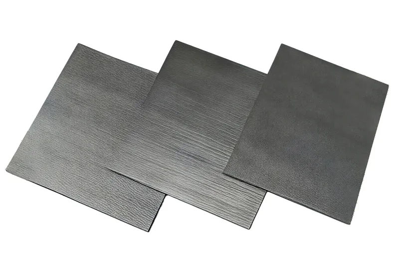
Short bursts of heat? Graphite smooths them out. Long loads? It keeps gradients low. Sheen Technology integrates these with composite manufacturing methods to keep high power density inverter designs stable without bulk.
Step 3: Integrating Heat Pipe Materials for Uniform Cooling
For serious high-power-density inverter thermal management, heat pipe technology steps in. It uses phase change materials and a working fluid to move heat fast between the evaporator section and condenser section.
Nested flow inside a heat pipe setup:
Core system:
- Wick-driven return via wick structures
- Vapor transport across the chamber
- Heat absorbed at hot zones
- Heat released at cooler fins
Liquid Cooling Vs Air Cooling Solutions
High-power-density inverter thermal management is where heat either gets handled smartly or turns into a real headache. When power density climbs, inverter cooling design choices start to matter a lot. This is where Sheen Technology steps in, balancing inverter heat management with practical system design.
Liquid Cooling
High-power-density inverter thermal management with liquid systems leans on controlled fluid motion and tight thermal contact. It’s not just about moving heat; it’s about moving it fast and evenly.
Core flow path
Coolant enters through a sealed loop
- passes across a Cold plate mounted on the Inverter
- absorbs concentrated heat via optimized Fluid dynamics
- heated liquid exits toward a Heat exchanger, transfers energy to ambient or secondary loop, cycle continues via a precision Pump
Thermal stability layers
- Primary control: flow rate tuning
- Secondary control: Radiator sizing
- Fine adjustment: coolant composition (glycol vs dielectric fluids)
Performance notes
- high heat flux removal supports compact inverter cooling layouts
- reduced thermal gradients protect sensitive components
- ideal for high power density inverter cooling where air hits limits
Air Cooling
Air-based high-power-density inverter thermal management feels simpler but comes with trade-offs. Still, for many setups, it gets the job done without complexity.
Quick breakdown:
- Fan drives Airflow
- heat spreads across Heatsink with dense Fins
- Convection pushes heat into Ambient air
Performance comparison snapshot:
| Parameter | Air Cooling | Liquid Cooling | Impact on Inverter Cooling |
| Heat capacity | Low | High | Limits air in high power density inverter cooling |
| System cost | Low | Medium–High | Air wins on budget |
| Maintenance | Minimal | Moderate | Air easier to manage |
| Cooling uniformity | Medium | High | Liquid better for inverter heat management |
| Size efficiency | Larger | Compact | Liquid suits dense layouts |
Short notes:
- Air cooling struggles when inverter thermal density spikes
- Ducting design can improve airflow, but only to a point
In high-power-density inverter thermal management, air still has a place, just not at the extreme edge where liquid clearly takes over.
Are Your Heat Pipes Underperforming?
Tight layouts and rising loads make high power density inverter thermal management a daily headache. When high-power-density inverter thermal management slips, heat pipes often get blamed—but the real story is messier. From inverter thermal management tuning to high power density thermal management choices, small material issues can quietly cap performance.
Diagnosing Blockages in Heat Pipe Materials
blockages in heat pipes don’t shout; they whisper through rising temps and uneven spreading.
Quick checks:
- Look for defects: dents, kinks, or wick collapse
- Track flow behavior via temperature gradients
- Compare baseline performance after load steps
Deeper diagnosis
Material path
· Inspect materials purity; residues clog capillaries
· Verify working fluid compatibility
Internal health
· Wick integrity under cycling
· Gas contamination causing dry-out
Small fixes—cleaning, re-evacuation—can restore high-power-density inverter thermal management without redesign. Sheen Technology often flags these hidden culprits early, saving rebuild time.
Upgrading to Vapor Chamber Materials for Higher Flux
When heat spikes, vapor chambers spread it faster than pipes.
Selection path
- Match materials to peak heat flux
- Favor high thermal conductivity bases
Mechanism
- phase change distributes load laterally
- Low resistance improves heat transfer
Outcome
- Better performance in dense boards
- Smoother thermal management for high power density inverter thermal management
Short notes: thinner stacks, fewer hotspots, easier inverter thermal management tuning.
Ensuring Proper Nickel Plating and Solder Alloy Seals
Good seals keep the physics honest.
Surface protection
- nickel plating blocks corrosion
- Enhances adhesion for joins
Joint integrity
- Choose stable solder alloy
- Verify seals for full hermeticity
Manufacturing discipline
- Controlled atmospheres
- Leak testing tied to reliability
Multiple short takes: poor plating flakes; bad alloys creep; tiny leaks wreck pressure balance. Nail these, and high-power-density inverter thermal management stays consistent.
Scenario: EV Charging Station Thermal Strategy
Fast charging isn’t just about power; it’s about keeping things cool when currents spike and hardware gets pushed hard. This guide walks through practical cooling ideas tied to High-power-density inverter thermal management, blending fluid, material, and storage tricks that keep stations stable, efficient, and ready for daily abuse.
High Flow Deionized Water Loops for Fast Charging Stations
deionized water, cooling loops, and tuned flow rate keep heat transfer sharp in charging stations
- Start with fluid dynamics modeling
- Size pumps for fast charging peaks
- Maintain resistivity to protect power stacks
In practice, thermal management for high power density inverter setups thrives on steady flow and clean fluid. Small tweaks in loop routing can shave hotspots quickly.
Integrating Glycol Water Mixtures with Aluminum Silicon Carbide Sinks
| Coolant mix (%) | Thermal conductivity (W/m·K) | Sink type | ΔT reduction (%) |
| 30 glycol water | 0.42 | aluminum silicon carbide | 18 |
| 40 coolant | 0.39 | composite heat sinks | 22 |
| 50 cooling fluid | 0.36 | hybrid thermal interface | 25 |
- Pairing coolant chemistry with material integration matters
- thermal conductivity gains show up fast under inverter load
Combining Silicone Rubber Insulation with Copper Foil Traces
- silicone rubber adds dielectric material strength
- copper foil boosts heat dissipation across circuit traces
Short bursts of heat from power electronics spread quickly when foil paths are tight and insulation stays flexible. That combo supports high-power-density inverter cooling without cracking or leakage risks.
Employing Phase Change Materials in Station Control Units
Embed phase change materials near hotspots
- Use latent heat to buffer spikes
- Stabilize control units temperature
Sync with inverter load cycles
- Improve temperature stability
- Extend electronics life
This layered thermal regulation approach fits neatly into high-power-density inverter thermal management, smoothing sudden loads. Sheen Technology integrates PCM blocks with sensors so cooling reacts in real time, not after the heat hits.
【Request a Custom Quote】Not sure which thermal management solution fits your high-power-density inverter, EV charging station, power module, or energy system design? Send us your operating temperature range, power density, insulation requirements, interface conditions, and reliability targets, and our engineers can help recommend the right thermal solution for your application.
Sheen Thermal
Dongguan Sheen Electronic Technology Co., Ltd · Founded in 2008
Manufacturer of thermal interface materials and silicone foam for automotive electronics, energy storage, power electronics, communications and consumer electronics.
Certified
- ISO 9001:2015
- ISO 14001:2015
- IATF 16949:2016
What we supply
- Thermal conductivity Up to 90 W/m·K
- Thickness 0.3–10.0 mm
- Custom & samples Die-cut to drawing, 3–7 days