
 English
 usheenthermal

Phase Change Thermal Interface Material vs. Traditional Thermal Pads
Date:2026-09-23
Choosing a phase change thermal interface material or traditional thermal pad can make or break thermal performance, assembly fit, and production flow. Phase change TIM forms a thin interface when heated; pads stay compressible, bridging larger gaps and handling tolerance swings.
For volume sourcing, conductivity isn’t the whole ball game. Compare impedance, thickness, hardness, dielectric strength, temperature behavior, storage, compliance, and lot consistency before sampling. This guide shows where each option fits, from CPU and GPU heatsinks to power modules and server hardware.
Key Points for Phase Change Thermal Interface Material
➔ Thermal Performance: Softens at operating temperature to form ultra-thin bond lines, reducing thermal impedance versus conventional pads.
➔ Gap Filling: Self-adjusting viscosity wets micro-gaps automatically, improving contact on CPUs, GPUs, and power modules.
➔ Installation & Cleanliness: Solid at room temperature—no oil bleed or messy residue—while delivering repeatable application and minimal cleanup.
➔ Supply & Reliability: Specify phase change temperature, dielectric strength, storage guidelines, and lot consistency for high-volume server and data-center deployments.
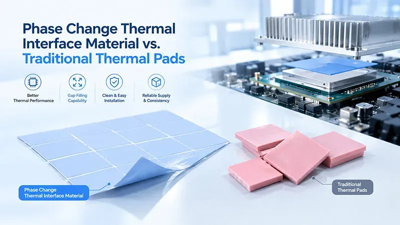
What Are Thermal Interface Options?
A good thermal interface closes tiny air spaces so heat can reach the cooler faster. From thermal interface material to phase-change thermal interface material, the right choice depends on gap size, mounting pressure, electrical needs, and assembly method.
| Option | Gap tolerance | Typical role | Principal constraint |
| Phase-change sheet | Small, tightly controlled | CPU / GPU to heatsink; thin, repeatable joints | Needs enough clamp pressure and contact area; transition temperature must sit below the joint’s lowest steady-state operating point |
| Thermal pad (gap filler) | Moderate to large; tolerant of height variation | Multiple components of differing heights; power modules; no clamp hardware | Through-plane conductivity is low relative to a film; thicker pad means proportionally higher impedance |
| Dispensable paste / gel | Small; fills surface texture only | Automated dispensing onto dies and heat spreaders; high-volume lines | Requires dispensing control and cure or wet-out time; pump-out risk under thermal cycling |
| Thermally conductive tape | Small to moderate | LED and substrate mounting where mechanical attachment is also needed | Adhesive layer adds impedance; load-bearing capacity limited |
Gap Filler Pad: Bridging Uneven CPU and Power Module Surfaces
A gap filler pad works well when a CPU surface and nearby power module parts sit at different heights.
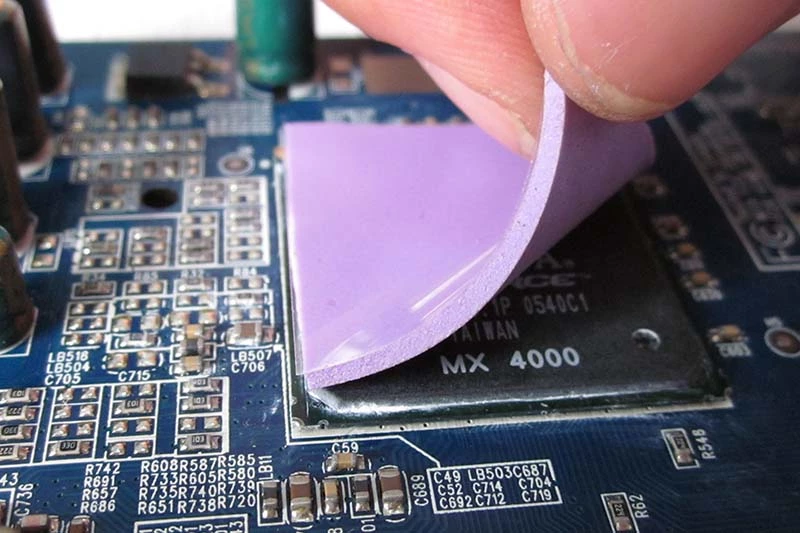
Fit and thermal path
- A soft pad follows each surface irregularity, cutting trapped air.
- Suitable thermal conductivity supports steady heat dissipation without needing perfect contact.
Practical choice
- Thickness should cover the gap without excessive compression.
- Hardness matters too; softer grades put less stress on delicate parts.
Unlike a phase change thermal interface material, a pad can bridge much larger gaps. That makes installation pretty straightforward.
Dispensable Paste with Boron Nitride for GPU Heatsinks
Dispensable paste flows into microscopic spaces between a chip and a GPU heatsink, where low viscosity can aid spreading and automated dispensing. Boron nitride raises thermal conductivity while providing electrical insulation.
Proper dispersion keeps filler evenly distributed. In microprocessor cooling, that consistency helps avoid hot spots; compared with phase change material, paste also arrives ready to conform during assembly.
Silicone-Matrix Thermal Grease in IGBT Packaging
For IGBT packaging, grease forms a very thin contact layer:
A silicone matrix carries thermally conductive fillers such as alumina.
- Thin spreading lowers thermal resistance.
- Good coverage limits insulating air pockets.
Stable thermal grease supports demanding power electronics.
- Pump-out prevention matters through repeated heating cycles.
- Better interface contact helps control junction temperature.
A phase change thermal interface material offers another route, changing consistency near its designed transition temperature to improve surface contact.
Adhesive Tape (Flexible Sheet) for LED Substrate Integration
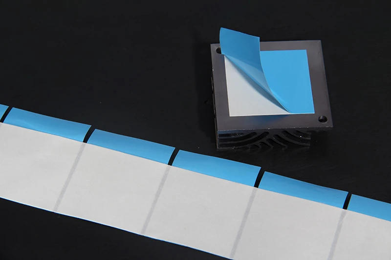
Adhesive tape combines bonding and thermal management in one flexible sheet, which can simplify assembly.
- For an LED substrate, controlled thickness creates a repeatable heat transfer path to the heatsink.
- Roll formats and release liners suit fast production.
- In optoelectronics, the adhesive layer can replace separate mounting hardware where loads permit.
Unlike thermal grease or phase change thermal interface material, tape stays put and provides mechanical attachment and thermal contact.
4 Benefits of Phase Change TIM
A phase change thermal interface material helps processors shed heat by changing behavior as temperatures rise. In practical hardware, that means better contact, easier handling, and steady cooling where it counts most.
| Properties | Color | Thermal Conductivity | Thermal Impedance (@50psi) | Thickness | Phase Change Temp. |
| Unit | - | W/m·K | ℃*in2/W | mm | ℃ |
| SP205A-30 | Gray | 3.0 | 0.05 | 0.2 | 45 ~ 55 |
| SP205A-35 | Gray | 3.5 | 0.04 | 0.2 | 45 ~ 55 |
| SP205A-40 | Gray | 4.0 | 0.03 | 0.2 | 45 ~ 55 |
| SP205A-50 | Gray | 5.0 | 0.02 | 0.3 | 45 ~ 55 |
| SP205A-60 | Gray | 6.0 | 0.015 | 0.3 | 45 ~ 55 |
| SP205A-L-80 | Gray | 8.0 | 0.007 | 0.15 | 50 ~ 70 |
| SP350P | Green | 1.8 | 0.4 (30psi) | 0.13 ~ 0.5 | 45 ~ 55 |
| Test Method | Visual | ASTM D5470 | ASTM D5470 | ASTM D751 | ASTM D3418 |
Enhanced Thermal Conductivity Lowers Hot-Spot Temperatures
A phase change thermal interface material combines a conductive filler with a heat-sensitive matrix, helping move energy away from concentrated hot areas.
Better thermal conductivity
- Improves heat dissipation between the processor and heatsink.
- Supports temperature reduction at each hot-spot, where concentrated heat can limit performance.
Better contact
- As phase change TIM softens, tiny voids shrink.
- Improved contact can raise cooling efficiency and stabilize overall thermal performance. Pretty handy when processor loads jump quickly.
Reduced Thermal Impedance for Faster CPU Cooling
Once warmed past its activation range, phase change thermal interface material can form a thinner bond line than many conventional pads. Less material between surfaces can mean lower thermal impedance.
- Heat leaves the processor junction.
- The softened phase change layer improves heat transfer across the contact.
- Lower thermal resistance can support faster CPU cooling and a better cooling rate.
Performance depends on thickness, pressure, temperature, and material formulation; ASTM D5470 testing is commonly used to characterize thermal transmission properties.
Self-Adjusting Viscosity Fills Micro-Gaps Automatically
The clever bit happens during heating: the phase change thermal interface material softens, allowing its viscosity to decrease without behaving like ordinary liquid grease.
During warm-up:
- Phase change begins near the designed activation temperature.
- Softer material flows into microscopic micro-gaps.
At the contact:
- Improved filling increases surface contact.
- The interface conforms to small surface variations through automatic adjustment.
This thermal interface approach can create closer contact without requiring a thick, highly compliant pad.
Cleaner Installation with Minimal Oil Bleed and Residue
Room-temperature solidity makes installation less messy and simplifies application during assembly. That can be a big deal for production lines.
Clean handling: Properly formulated phase change TIM can limit oil bleed, including migration associated with silicone oil, while reducing excess residue around components.
Long-term use: Controlled material movement supports cleanliness across thermal cycles and can make later maintenance easier. Sheen Technology phase change TIM solutions can be considered where repeatable placement and tidy handling are key design priorities.
Phase Change TIM vs. Thermal Pads
Choosing between a phase change thermal interface material and a pad comes down to gap size, pressure, service temperature, and assembly needs. Both move heat from hot components, but their physical behavior differs quite a bit once real operating conditions kick in.
| Criterion | Phase-change sheet | Thermal pad | Deciding question |
| Gap size and tolerance | Small; needs closely controlled, parallel surfaces | Moderate to large; tolerant of height variation and non-parallel surfaces | Can the two surfaces be held close and parallel? |
| Mounting pressure | Requires positive clamp pressure to collapse the bond line | Works under low or non-uniform pressure | Is there hardware to apply and maintain clamp load? |
| Achievable bond line | Very thin — this is its main thermal advantage | Set by pad thickness, which cannot fall below the gap it fills | How thin can the interface actually get? |
| Thermal impedance | Low, and dominated by bond-line thickness | Higher; scales with thickness and the pad’s through-plane conductivity | What is the impedance at the operating bond line, not at the nominal one? |
| Electrical behaviour | Insulating in the standard filled formulations; verify by specification | Filled elastomers provide dielectric breakdown strength — often the reason a pad is chosen | Is isolation a requirement, and at what voltage? |
| Re-workability | Usually a one-time placement; rework means replacing the film | Can often be reused or replaced without re-dispensing | Will the joint be opened in service or during build? |
| Where it belongs | CPU and GPU to heatsink, power modules, thin controlled joints | Multi-height assemblies, power modules without clamps, thermal paths to chassis | — |
Phase Change TIM
A phase change thermal interface material begins relatively firm, then softens as the interface reaches its designed phase transition temperature. That change helps the thermal material spread into tiny surface defects without the mess of conventional grease.
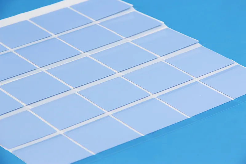
Heat-transfer behavior
- Better micro-void filling can lower contact resistance between a processor and heatsink.
- A thin bond line can make good thermal conductivity more useful in practice, since heat travels through less material.
Mechanical behavior
- Proper formulation can limit the pump-out effect, where TIM moves away from the contact area.
- Long-term reliability depends on mounting pressure, temperature cycling, and compatible surfaces.
Sheen Technology can match phase change TIM options to processor cooling designs where controlled thickness and clean assembly are key goals.
Thermal Pads
Thermal pads take a different route: they stay solid, squish into place, and handle uneven gaps pretty well. Their elastomer construction, commonly based on silicone material, makes installation straightforward.
- Check the mechanical gap and choose enough thickness tolerance to maintain contact despite part variation.
- Apply suitable compression. Too little can leave air pockets; too much may strain components or reduce pad life.
- Consider electrical needs. Specified dielectric breakdown performance can provide useful insulation where conductive parts sit close together.
Pad thickness matters because a longer heat path can raise thermal impedance, even when the material itself conducts heat well. That tradeoff is often worthwhile for assemblies with wider gaps or uneven component heights.

For production teams, easy installation is a practical win: precut thermal pads simplify placement, while phase-change interface materials are generally better suited to thin, closely controlled processor-to-heatsink joints.
Why Choose Phase Change TIM?
A phase change thermal interface material gives high-power electronics a practical way to move heat across imperfect mating surfaces. Once warm, the phase change layer softens and settles into tiny surface gaps. Sheen Technology develops these thermal interface solutions for GPUs, CPUs, and servers where steady cooling, clean handling, and dependable contact really count.
Superior GPU Heatsink Contact for High-Performance Graphics
A phase change thermal interface material responds to operating heat and mounting force, helping the GPU heatsink maintain close contact when graphics loads get tough.
Contact improvement
- The softened phase change layer fills microscopic voids that otherwise trap air.
- Lower contact resistance helps available thermal conductivity translate into useful cooling.
Performance benefits
- More consistent heat dissipation supports stable temperatures.
- Stable contact can help sustain graphics performance during long, high-power workloads.
That’s the practical payoff: fewer tiny air gaps standing between the chip and cooler.
Optimized CPU Cooling Across Fluctuating Phase Change Temperatures
For CPU cooling, choosing the right phase change temperature matters. A phase change thermal interface material should become workable around its intended operating range without turning messy during normal handling.
- As CPU temperature rises, changing viscosity lets the material improve surface contact.
- Controlled bondline thickness keeps the thermal path short.
- During repeated thermal cycling, suitable material properties help maintain contact despite temperature fluctuation.
Some formulations use phase-transition behavior associated with latent heat, although heat-transfer performance depends heavily on formulation and interface design. Sheen Technology can match phase change TIM characteristics to the actual CPU temperature range rather than taking a one-size-fits-all approach.
Proven Dielectric Strength and Thermal Stability in Demanding Servers
A server-ready phase change thermal interface material needs more than an attractive conductivity figure.
Electrical performance
- Verified dielectric strength supports electrical insulation around sensitive hardware.
Thermal endurance
- Good thermal stability matters under sustained heat flux.
- Qualification should examine aging and repeated temperature cycles.
Deployment
- In enterprise servers, consistent application affects reliability.
Sheen Technology evaluates phase change materials with application demands in mind, helping support predictable long-term performance rather than relying on headline specifications alone.
Data Center Cooling: Phase Change TIM
A phase change thermal interface material can help crowded server racks move processor heat into cooling hardware with less contact resistance. For data-center teams, the trick is balancing thermal behavior, compliance, and storage discipline so phase change products remain practical from warehouse receipt through years of server operation.
Rack-Level Heat Transfer: Leveraging Melting Point for Rapid Dissipation
At rack-level cooling scale, a phase change thermal interface material softens near its designed melting point, filling small surface gaps between a processor and heatsink.
Thermal design
Match activation temperature to the expected processor range.
- As the material softens, improved contact can reduce interface resistance and support faster heat dissipation.
- Suitable thermal conductivity still matters; melting alone cannot fix an undersized heatsink.
Check server behavior under real workloads.
- Track junction temperature through repeated power cycles, not merely a short lab run.
This approach gives engineers a practical way to assess a thermal interface material without getting lost in spec-sheet numbers.
Meeting ISO 9001 and RoHS Compliance Under Continuous Load
Procurement needs paperwork and performance to line up. A phase change thermal interface material should therefore be reviewed across a few linked controls.
Supplier controls
- Verify ISO 9001 certification scope and quality management records.
- Confirm current RoHS compliance, applicable REACH documentation, and limits on regulated hazardous substances.
Application controls
- Run reliability testing at representative continuous load conditions.
- Record cycling, interface temperatures, and physical changes against internal regulatory standards.
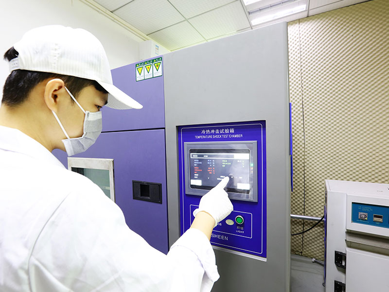
Sheen Technology can be evaluated through the same qualification workflow rather than relying on compliance labels as proof of thermal endurance.
Shelf Life and Storage Condition Guidelines for Large-Scale Deployment
For a large-scale deployment, a phase change thermal interface material also needs sensible warehouse care.
Receiving
- Record lot numbers and stated shelf life.
- Inspect packaging and release liners.
Warehousing
- Follow manufacturer storage conditions and temperature control ranges.
- Respect stated humidity limits to protect handling quality and material stability.
Deployment
- Use first-expiring stock first through disciplined inventory management.
- Keep unopened material within supplier limits until installation; simple housekeeping here can save a lot of hassle later.
【Request a Custom Quote】: share your joint geometry, clamp pressure, required isolation voltage, and operating temperature range with Sheen’s engineering team to compare phase-change film and pad samples under your conditions.
Sheen Thermal
Dongguan Sheen Electronic Technology Co., Ltd · Founded in 2008
Manufacturer of thermal interface materials and silicone foam for automotive electronics, energy storage, power electronics, communications and consumer electronics.
Certified
- ISO 9001:2015
- ISO 14001:2015
- IATF 16949:2016
What we supply
- Thermal conductivity Up to 90 W/m·K
- Thickness 0.3–10.0 mm
- Custom & samples Die-cut to drawing, 3–7 days
LAST:Nothing