
 English
 usheenthermal

Data Analysis: Contact Thermal Resistance vs. Pressure in BN Pads
Date:2026-07-20
Data Analysis: Contact Thermal Resistance vs. Pressure in BN Pads
The Relationship between contact thermal resistance and pressure of boron nitride thermal pads decides if your device runs cool or quietly burns margin.
Contact thermal resistance (Rc) at the interface between a power semiconductor module and its heat sink is the single largest contributor to total junction-to-ambient thermal resistance in most power electronics assemblies. For boron nitride (BN) thermal pads — the preferred thermal interface material (TIM) for high-reliability power electronics — Rc is not a fixed value. It varies significantly with applied mounting pressure, pad thickness, filler morphology, and polymer matrix properties.
MarketsandMarkets and IDTechEx report surging demand for advanced thermal interface materials in power electronics, tied to electrification and stricter reliability expectations.
Pressure turns specs into performance.
Quick Insights: Relationship between contact thermal resistance and pressure of boron nitride thermal pads
Conformity under pressure reduces interface resistance, boosting heat flow.
Pad thickness and polymer matrix design govern compression response and thermal impedance.
Hexagonal BN filler networks deliver lower resistance than silicone at high pressures.
Uniform mounting pressure and torque control ensure junction-temperature reduction and cycling stability.
Relationship Between Contact Thermal Resistance And Pressure Of Boron Nitride Thermal Pads: Overview
Contact thermal resistance is closely related to pressure; pressure increases the effective contact area, thereby reducing contact thermal resistance. In practical hardware applications, pressure determines the degree of conformity (or "wetting") between the thermal pad and the surface, which in turn influences the path of heat flow. Factors such as contact thermal resistance, pressure, thermal pad design, and material selection collectively determine the actual thermal performance of the thermal pad.
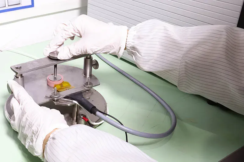
Measuring contact thermal resistance under varied pressure loads
Sheen Technology Laboratory's procedural workflow for measuring contact thermal resistance in Boron Nitride (BN) thermal pads and other thermal interface materials (TIMs):
Setup
- Calibrate heat flux sensors; align plates for uniform load
- Fix sample thickness; log ambient drift
Load sweep
- The initial pressure is 10 psi, the pressure increment is 10 psi, and the final pressure is 40 psi.
- Capture experimental data: ΔT, heat flux, compression
Reduction
- Compute Rc = ΔT / q
- Plot contact resistance vs pressure to reveal the relationship between contact thermal resistance and pressure of boron nitride thermal pads
Validation
- Repeat cycles; check hysteresis and recovery
- Compare runs to confirm thermal performance
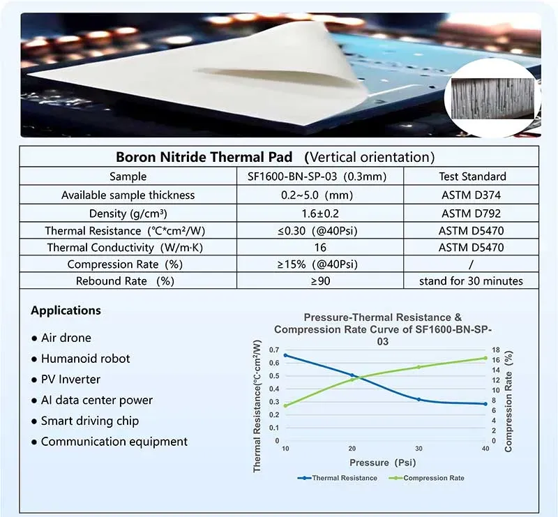
Short notes: higher pressure improves interface conformity; surface roughness still bites.
Influence of pad thickness and polymer matrix structure
How pad thickness and polymer matrix structure steer thermal resistance:
Thickness effect
- Thicker pads → longer conduction path
- More compliance → better wetting at low load
Matrix + filler morphology in composite materials
- BN platelets form networks under compression
- Dispersion quality governs percolation and heat paths
Net result
- The relationship between contact thermal resistance and pressure of boron nitride thermal pads tightens as networks densify
Sheen Technology provides BN pads in calibrated thickness increments to allow engineers to select the optimal trade-off between thermal impedance and mechanical compliance for their specific assembly conditions.
Boron nitride pads vs. silicone pads pressure response
Comparative map of boron nitride pads and silicone pads in pressure response:
Low pressure
- Silicone: high compliance, decent contact
- BN: slightly higher Rc until networks engage
Mid–high pressure
- BN networks activate → lower contact thermal resistance
- Silicone relies on squeeze, gains taper off
Application view
- Power modules favor BN for sustained loads
- Light clamping favors silicone
For power electronics applications where sustained clamping pressure of 0.5 MPa or higher is standard (traction inverters, PV inverters, industrial drives), BN pads are the clear engineering choice.
Key Factors Influencing BN Pad Performance
Getting the relationship between contact thermal resistance and pressure of boron nitride thermal pads right isn't just lab talk — it directly affects real cooling results. From BN pads in tight assemblies to uneven interfaces, small material tweaks shift thermal performance fast. Let's break down how pressure, structure, and composition quietly control contact resistance and heat flow.
Compressibility: Key to pressure-dependent thermal impedance
The relationship between contact thermal resistance and pressure of boron nitride thermal pads hinges on how compressibility responds under load:
Pressure interaction
- Low pressure → poor interface fit → higher contact resistance
- Moderate pressure → improved conformity → lower thermal impedance
- Excess pressure → diminishing returns, possible material fatigue
Material response
- Soft BN pads adapt to micro-gaps
- Elastic recovery maintains long-term thermal performance
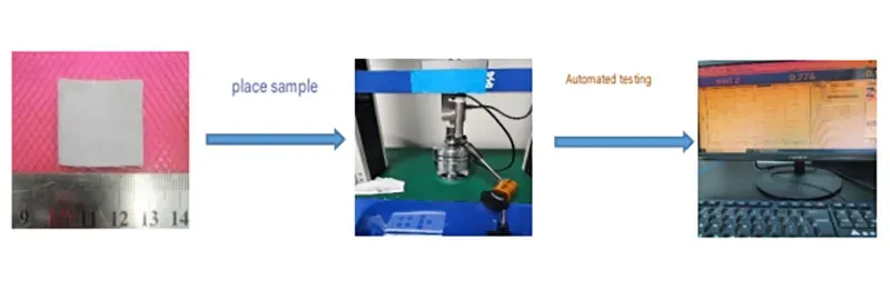
Sheen Technology Lab: Compressive Stress Test for Boron Nitride Thermal Conductive Pads
- Testing is performed using a computer-controlled electronic universal testing machine (10 kN) in accordance with ASTM D575.
- Sample preparation: Material dimensions of 25 mm × 25 mm × 2 mm.
Test method:
- Zero the force reading before testing; apply a 2 N force to bring the probe into contact with the sample surface.
- For the compressive stress test, set the compression speed to 0.5 mm/min and the deformation range to 10–50%. For the residual stress test, set the compression speed to 0.5 mm/min and the hold time to 600 seconds.
- Start the test; the result is automatically generated. The value is 40 psi.
| Test Item | Test Data | |||||
| Sample | 10% | 20% | 30% | 40% | 50% | |
| Instantaneous stress (psi) at 10–50% deformation | 1 | 21.80 | 38.51 | 69.42 | 101.14 | 168.26 |
| 2 | 17.65 | 34.12 | 60.32 | 89.35 | 150.37 | |
| 3 | 16.35 | 31.28 | 54.36 | 78.24 | 142.35 | |
| Average Value | 18.60 | 34.63 | 61.36 | 89.57 | 153.66 | |
| Residual compressive stress at 50% deformation | Sample | 1 | 2 | 3 | Average Value | |
| 40.61 | 34.96 | 27.62 | 34.40 | |||
In short bursts: better compression, tighter contact, smoother heat flow.
High thermal conductivity through optimized hexagonal boron nitride
- Align hexagonal boron nitride (hBN) within the filler network
- Improve crystal structure pathways
- Stabilize heat transfer under pressure shifts
This tuning directly supports the contact thermal resistance and pressure of boron nitride thermal pads balance, where thermal conductivity and pressure act together, not separately.
Hexagonal BN (hBN) Crystal Structure Alignment
The platelet morphology of hexagonal BN particles creates anisotropic thermal conductivity within the pad. Under compression, BN platelets tend to align with their basal planes perpendicular to the heat flow direction, maximizing through-plane conductivity.
This alignment effect is pressure-dependent: higher pressure increases platelet orientation, which further reduces Rc beyond what compressibility alone would predict. This is why BN pads show a steeper Rc reduction vs. pressure compared to isotropic filler materials such as alumina or AlN.
Surface Topography and Hardness Balance
The mating surface roughness (Ra 0.8–3.2 µm typical for machined aluminum heat sinks) interacts with pad hardness to determine effective contact area at a given pressure.
- Pad too hard: insufficient deformation into micro-grooves, leaving air gaps that elevate Rc
- Pad too soft: excessive deformation risks extrusion beyond the mounting footprint and reduced dielectric strength at thin spots
Sheen Technology BN pads are formulated with a target durometer (Shore 00-50 to 00-80) that balances these competing requirements for typical power module surface finishes.
Surface Energy and Interface Wetting
The surface energy of the BN pad's silicone matrix determines how well it wets the mating surfaces at the microscopic level. Higher surface energy improves wetting and reduces the pressure required to achieve a given Rc target.
In sealed power module assemblies, outgassing behavior under compression is also relevant. Sheen Technology BN pads undergo vacuum outgassing verification (<0.1% weight loss at 125 °C) to ensure compatibility with sealed enclosure environments.
Sheen Technology provides detailed technical datasheets for BN thermal pads. Download the BN Pad Engineering Datasheet for complete pressure-performance characterization data and thermal simulation support files.
Practical Engineering Recommendations for Pressure Optimization
Understanding the Rc vs. pressure relationship is only useful if it translates to better designs. The following recommendations address the most common pressure-related issues in power module assembly.
Heat Sink Attachment Best Practices
Achieving consistent pressure across the interface requires attention to three factors:
- Surface flatness: Target <50 µm deviation across the mounting area. Machined aluminum heat sinks should be verified for flatness, particularly after anodizing, which can introduce warpage.
- Surface cleanliness: Remove all machining debris and oxidation with isopropyl alcohol (99%+ purity). Even 10 µm particles can create local high spots that reduce effective contact area.
- Torque specification: Use a calibrated torque wrench with a cross-tightening pattern. Apply 70% of target torque in the first pass, then 100% in the final pass to ensure uniform pressure distribution.
Short notes: uneven force spikes thermal resistance; steady load improves performance. The relationship between contact thermal resistance and pressure of boron nitride thermal pads shows a clear drop in resistance as pressure rises — until saturation.
Pressure application methods for thermal gap fillers
- Bolted assemblies (most common): Clamping screws with controlled torque provide repeatable pressure. Use Belleville washers or spring washers to compensate for thermal expansion and maintain consistent pressure over temperature.
- Spring-loaded assemblies: Compression springs mounted behind the heat sink maintain near-constant pressure through thermal cycling. This is the preferred method for applications with wide temperature swings.
- Clip or latch assemblies: Provide rapid assembly but less pressure control. Suitable for lower-power modules where thermal demands are less stringent.
Sheen Technology offers application-specific mounting guidelines for each of these assembly types, including recommended pad thickness, torque values, and spring specifications.
Impact on junction temperature reduction and thermal cycling stability
When the Rc vs. pressure relationship is properly optimized, the measurable impact on system performance includes:
- Junction temperature reduction of 8–15 °C at the operating pressure plateau (0.5–0.7 MPa)
- Improved thermal cycling endurance: lower peak temperatures reduce the delta-T that drives solder fatigue and bond wire lift-off
- Stable thermal resistance over life: proper pressure prevents the Rc increase that occurs when pads lose contact through relaxation or creep
Sheen Technology BN pads are engineered to maintain their compression characteristics through 2,000+ thermal cycles, ensuring that the Rc vs. pressure curve at installation is the same curve the system follows years later.
Explore BN Thermal Pad Applications. Sheen Technology BN thermal pads are deployed across power electronics applications where pressure-dependent thermal performance is critical, including traction inverters for EV/HEV, PV inverters, industrial motor drives, wind turbine converters, and railway traction systems. Visit www.sheenmaterials.com/applications/ for application notes, reference designs, and case studies showing how BN pads are specified and integrated across different power levels, voltage classes, and thermal budgets.
Request a Technical Datasheet or Engineering Sample. Sheen Technology provides BN thermal pads in thicknesses from 0.5 mm to 5.0 mm, with custom die-cutting and adhesive backing options for high-volume production. Contact our thermal engineering team for a technical datasheet, free sample kit, or application-specific thermal simulation support.
Sheen Thermal
Dongguan Sheen Electronic Technology Co., Ltd · Founded in 2008
Manufacturer of thermal interface materials and silicone foam for automotive electronics, energy storage, power electronics, communications and consumer electronics.
Certified
- ISO 9001:2015
- ISO 14001:2015
- IATF 16949:2016
What we supply
- Thermal conductivity Up to 90 W/m·K
- Thickness 0.3–10.0 mm
- Custom & samples Die-cut to drawing, 3–7 days