
 English
 usheenthermal

Mastering Thermal Resistance Fundamentals for Thermal Design Success
Date:2026-08-06
Thermal Resistance Fundamentals for Thermal Design isn't theory—it's the line between products that ship and ones that fail hot, slow, and expensive.
Sheen Technology engineers note interface quality and assembly control dictate real thermal resistance.
Pick materials like commodities; pay in failures, rework, and cooling costs stack fast.
Key Points & Quick Notes: Thermal Resistance Fundamentals for Thermal Design
➔ Material Selection: Balance conductivity, cost, and weight—copper excels in heat spreading, aluminum wins on cost and weight.
➔ TIM Optimization: Choose grease for ease, phase-change for cycling, liquid metal for peak conductivity—watch compatibility.
➔ Network Modeling: Series resistances stack linearly; parallel paths via vias or spreaders slash overall Rθ.
➔ PCB Layout: Strategically place heat pipes, use multiple filled thermal vias, and boost copper weight or consider ceramic/metal-core substrates.
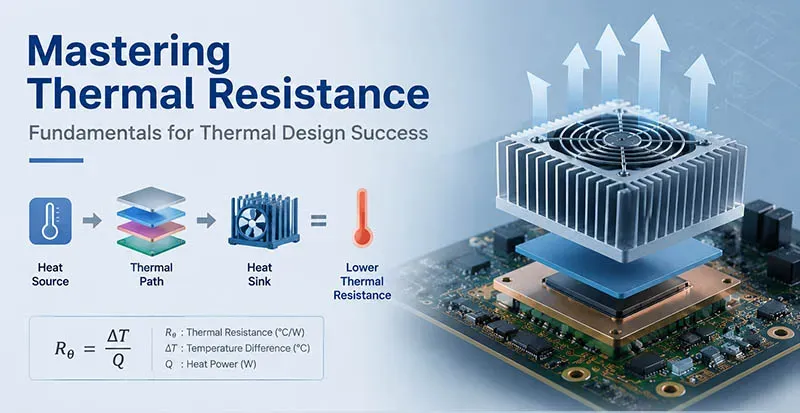
Factors Affecting Thermal Resistance
Getting a grip on Thermal Resistance Fundamentals for Thermal Design means breaking heat flow into real-world choices—materials, interfaces, substrates, and packaging. Keep it simple: lower resistance, smoother heat transfer, better reliability. These fundamentals for thermal design show up everywhere, from chips to power modules.
How Aluminum vs Copper Heat Sinks Influence Thermal Conductivity
Aluminum, Copper, and Heat Sink choices shape Thermal Conductivity and overall Thermal Design.
1) Material behavior
- Copper: higher Heat Transfer, faster spreading
- Aluminum: lighter, easier forming
2) Design trade-offs
- Cost vs performance
- Weight vs durability
Short take: copper wins raw performance; aluminum keeps systems practical.
TIM Choices: Grease, Phase Change Materials, Liquid Metals Compared
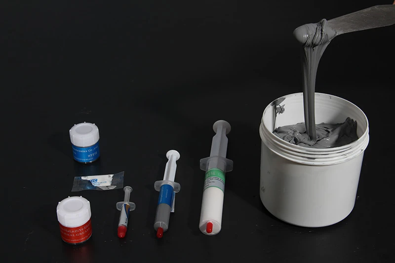
Key TIM types: Thermal Grease, Phase Change Material, Liquid Metal
Flow of selection:
- Define interface gap
- Match Thermal Interface behavior
- Minimize Interface Resistance
For tight Thermal Resistance Fundamentals for Thermal Design, liquid metal leads, but handling isn’t casual.
Substrate Selection Impact: FR-4, Alumina and Polyimide Explained
Substrate matters in PCB heat paths:
- FR-4 → cheap, weak Thermal Management
- Alumina → solid Dielectric, better conduction
- Polyimide → flexible, mid-range performance
Nested view:
- Electrical need: insulation, signal stability
- Thermal need: spreading, dissipation
Balancing both defines real fundamentals for thermal design.
Encapsulation Challenges: CTE Mismatch in Epoxy and Silicone
⚠ Encapsulation issues often hide in CTE Mismatch
Multi-step reality:
- Heat cycle begins
- Epoxy or Silicone expands unevenly
- Thermal Stress builds
- Cracks or delamination hit Reliability
Quick fixes:
- match material CTE
- control curing
- validate under cycling
Teams working on Thermal Resistance Fundamentals for Thermal Design often lean on partners like Sheen Technology to fine-tune packaging choices without overengineering.
Resistance Networks: Series And Parallel Models
A quick, practical guide to Thermal Resistance Fundamentals for Thermal Design, breaking down how heat actually moves through stacked layers and branching paths, so your thermal design feels less guessy and more dialed-in.
Series Networks
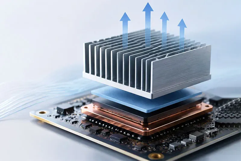
In a sequential path, heat transfer behaves like a single-file line; every layer adds thermal resistance, shaping the overall temperature gradient.
Material stack thinking
- TIM → substrate → spreader → sink
- Each layer contributes to total resistance in conduction
- Weak interfaces in composite materials quietly dominate performance
Thermal design fundamentals in practice
- Calculate layer-by-layer
- Sum all thermal resistance values
- Map the resulting temperature gradient across thickness
- Validate with measurements; tweak interfaces before bulk materials
Optimization loop
- Reduce contact resistance
- Upgrade high-R layers
- Recheck total resistance
Short takeaways:
- Bad interface = big penalty
- Thin doesn’t always mean low resistance
- Smooth stacking wins
For teams applying Thermal Resistance Fundamentals for Thermal Design, Sheen Technology keeps interfaces tight and predictable, which trims surprises in conduction paths.
Parallel Networks
When heat splits into parallel paths, overall resistance drops as flow shares the load, boosting heat dissipation.
Path architecture
- Vias, fins, and spreaders create branching
- Larger effective area improves convective heat transfer
- Surface treatments can aid radiative heat transfer
Calculation mindset
- Treat each branch as a resistor
- Combine using parallel formulas for thermal resistance
- Identify dominant low-R branches that carry most heat
Design moves
- Add vias or widen spreaders
- Balance branches to avoid hotspots
- Pair with airflow to amplify convection
Quick mix:
- More branches → lower overall resistance
- Uneven paths → uneven temperatures
- Airflow multiplies gains
Applied Thermal Resistance Fundamentals for Thermal Design shines here; Sheen Technology solutions help expand parallel paths without bloating size, keeping heat dissipation efficient and steady.
PCB Layout: Minimizing Thermal Resistance
Thermal resistance fundamentals for thermal design can feel a bit abstract, but in real PCB work it’s all about heat paths, materials, and smart placement. Get the thermal design basics right, and performance follows naturally.
Step 1: Strategic Placement of Heat Pipes and Vapor Chambers
Dialing in heat pipes and vapor chambers starts with thermal resistance fundamentals for thermal design and a grounded placement strategy:
Identify hotspots
- Map thermal management zones using power density
- Flag tight clusters where heat transfer stalls
Align cooling solutions
- Place vapor chambers directly under peak loads
- Route heat pipes toward airflow exits
Reduce gradients
- Shorten distance between source and sink
- Balance spreading for smoother thermal design behavior
Done right, the thermal resistance thermal design loop tightens, and temps stop spiking.
4 Via Design Tips for Lower Thermal Resistance
When working through thermal resistance fundamentals for thermal design, vias quietly do the heavy lifting:
Core tactics
Thermal vias density
- Increase via array count
- Tight pitch near hotspots
Geometry tuning
- Larger diameter improves thermal conductivity
- Shorter via length cuts thermal resistance
Material boost
- Fill vias to enhance heat dissipation
This layered approach strengthens vertical heat flow in any PCB design.
Optimizing Copper Weight and Trace Width for Heat Spreading
Copper choices directly shape thermal resistance and thermal design outcomes. Wider PCB traces and higher copper weight spread heat faster, reducing local stress.
Quick mix:
- Thick copper for power zones
- Wide power traces for smoother heat spreading
- Balanced routing for even thermal conductivity
“Efficient thermal design at the board level can cut system cooling costs by over 20%,” notes a 2025 IPC industry update.
That insight lines up with thermal resistance fundamentals for thermal design—better spreading equals lower peak temps. Sheen Technology applies this logic in high-density layouts to keep boards stable under load.
Ceramic vs Metal Core PCB: Which Substrate Wins?
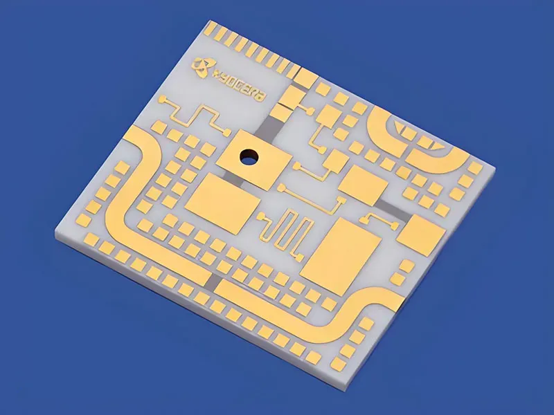
Ceramic PCB
- High thermal performance, excellent insulation, strong thermal conductivity. Cost runs higher.
Metal core PCB
- Solid heat dissipation, easier PCB manufacturing, budget-friendly for power designs.
Thermal resistance fundamentals for thermal design suggest picking based on load and cost balance. Sheen Technology often pairs substrate choice with real thermal resistance thermal design simulations to avoid guesswork.
【Request a Custom Quote】Not sure which materials, interface, or substrate strategy fits your thermal design? Send us your operating temperature range, power density, interface conditions, and reliability targets, and our engineers can help recommend the right thermal solution for your application.
Sheen Thermal
Dongguan Sheen Electronic Technology Co., Ltd · Founded in 2008
Manufacturer of thermal interface materials and silicone foam for automotive electronics, energy storage, power electronics, communications and consumer electronics.
Certified
- ISO 9001:2015
- ISO 14001:2015
- IATF 16949:2016
What we supply
- Thermal conductivity Up to 90 W/m·K
- Thickness 0.3–10.0 mm
- Custom & samples Die-cut to drawing, 3–7 days