
 English
 usheenthermal

Thermal Pads vs. Thermal Paste: An Engineering Comparison for Production-Grade Thermal Interface Material Selection
Date:2026-08-07
Choosing between thermal pads vs thermal paste can feel like picking the lesser evil in a sweaty tech showdown—one’s clean and convenient, the other’s messy but mighty.
Thermal interface material selection is a multi-variable engineering decision that directly affects production yield, field reliability, and total cost of ownership. For OEM assembly engineers and thermal designers, the choice between thermal pads and thermal paste is not about convenience versus performance — it's about matching TIM characteristics to specific production processes, reliability requirements, and application environments.
The global thermal interface materials market is projected to exceed $2.8 billion by 2026 (MarketsandMarkets, Thermal Interface Materials Market — Global Forecast to 2026), driven by AI computing, EV power electronics, and 5G infrastructure. This guide provides an engineering-level comparison of thermal pads and thermal paste across key performance parameters, with production-line integration context for volume manufacturing.
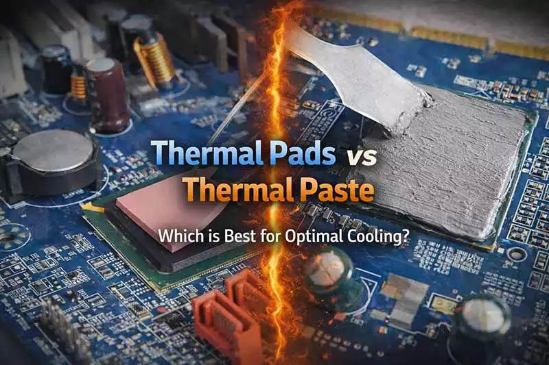
Key Factors to Consider: Thermal Pads vs Paste
Understanding Thermal Conductivity Performance in Thermal Pads and Paste
- Thermal conductivity is king here. Measured in Watt per meter-Kelvin (W/mK), it tells us how fast heat moves through a material.
- Sheen Technology's newly launched graphene thermal pad boasts a thermal conductivity of up to 90 W/m·K.
The higher the number, the better the heat transfer efficiency, especially for CPUs and GPUs under heavy loads.
Thermal Resistance: How Different Materials Impact Efficiency
- Lower thermal resistance means faster cooling.
- Pastes fill microscopic gaps more completely, reducing air pockets.
- Pads offer consistency but can leave micro-gaps if not compressed properly.
Interface thermal resistance (°C·cm²/W or °C·in²/W) combines bulk material resistance with contact resistance at both mating surfaces. Paste achieves lower minimum BLT (10–50 μm) than pads (100–500 μm), giving paste a theoretical advantage in interface resistance. However, pad BLT is controlled and repeatable; paste BLT is operator-dependent and varies 2–5× across production units without automated dispensing.
Electrical Insulation: The Role of Thermal Interface Materials
- Most thermal pads are naturally non-conductive—great news if you're working around sensitive PCBs or VRMs.
- Some pastes contain metal particles like silver or aluminum oxide, which can conduct electricity—watch out!
For production lines where 100% post-assembly electrical test is impractical, insulating pads provide a process-safety advantage.
Operating Temperature Range: Choosing the Right Material for Your Application
Both TIM types operate across typical electronics temperature ranges (-40°C to +150°C for standard grades, up to +200°C for high-temperature formulations).
The differentiation emerges under thermal cycling: paste is susceptible to pump-out (cyclic expansion/contraction squeezes material from the interface) and drying (volatile component evaporation). Pads, as cross-linked elastomers, resist both mechanisms but are subject to compression set (gradual loss of recovery force, ASTM D395). For applications requiring >5-year service life with minimal maintenance access, pad compression set data should be part of the material qualification package.
Production-Line Considerations — Pad vs. Paste
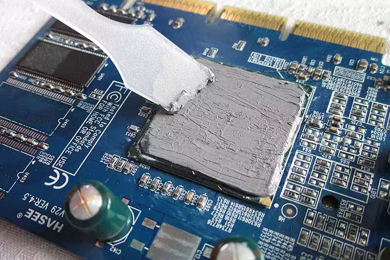
Automated Dispensing (Paste) vs. Pick-and-Place (Pads)
| Production Factor | Thermal Paste (Automated Dispensing) | Thermal Pad (Pick-and-Place) |
| Application Method | Pneumatic/auger valve dispensing with vision alignment | SMT pick-and-place from tape-and-reel or tray |
| Cycle Time (per unit) | 3–8 seconds (dispense + inspection) | 1–3 seconds (pick-and-place only) |
| Process Variability | Dispense volume ±5–15% (without closed-loop control) | Pad thickness ±5% (manufacturer-controlled) |
| Inspection Requirement | Inline vision for dispense volume and placement | Pre-placement vision; post-placement optional |
| Rework Complexity | Solvent cleaning + re-dispensing | Peel-off + re-place (no cleaning needed) |
| Throughput Sweet Spot | <5,000 units/day (dispense bottleneck) | >5,000 units/day (parallel placement heads) |
| Capital Equipment Cost | $15–50K per dispense station | Uses existing SMT placement equipment — marginal cost |
Material Handling and Shelf Life
Thermal paste has a typical shelf life of 6–12 months (unopened) and requires refrigeration for some formulations. Once opened, pot life may be measured in hours to days. Pre-cured thermal pads have 12–24 month shelf life at ambient conditions with no special handling. For production environments with intermittent demand or multi-shift operations, pad storage and handling logistics are significantly simpler.
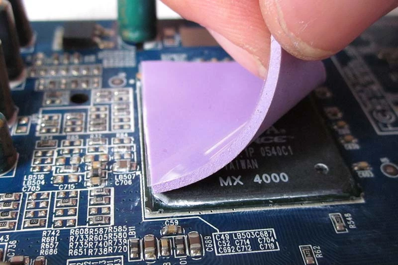
Quality Control and Traceability
Pad thickness, hardness, and thermal conductivity are verified by the manufacturer and documented per batch — incoming QC requires only dimensional spot-checking. Paste performance must be validated on the production line through dispense parameter optimization and periodic thermal impedance testing. Pad batch traceability (raw material lot → finished pad lot → production unit) is inherently simpler than paste traceability, which must also track dispense parameters, ambient conditions, and operator.
When to Choose Thermal Paste Over Thermal Pads
If you're stuck on the whole "thermal pads vs thermal paste" debate, this guide clears the air for high-performance scenarios.
High-Frequency Microprocessors and Thermal Paste
- CPU and high-end processor surfaces often have microscopic irregularities. Thermal paste fills those better than pads.
- For overclocked systems, thermal paste offers superior thermal conductivity, reducing temperature spikes.
- Unlike pads, pastes can be applied with a thinner bond line, maximizing contact between the die and the cooler’s base.
So if you’re pushing your gear hard—gaming rigs, rendering stations—paste is your best bet.
When to Opt for Thermal Paste in Power Electronic Components
Grouped Use Cases Where Paste Outperforms Pads:
- High-wattage MOSFETs and GaN transistors benefit from enhanced heat transfer via low-viscosity pastes.
- Devices with uneven mounting pressure need materials that spread evenly—pads can leave gaps; paste doesn’t.
- Applications requiring direct metal-to-metal contact—such as IGBT modules or inverter stages—rely on thin-layered compounds for consistent performance.
When it comes down to raw efficiency, especially under continuous loads, thermal paste doesn't just edge out pads—it dominates. And that’s not just talk; it’s backed by numbers.
How to Apply Thermal Paste for Optimal Performance
Getting the most out of your CPU or GPU starts with nailing the thermal paste application.
Surface Preparation Procedures for Effective Thermal Paste Application
Before you even touch the paste, surface prep is key. A clean base equals better heat transfer and longer component life.
- Use Isopropyl Alcohol Wipe both the CPU/GPU die and heatsink base with at least 90% isopropyl alcohol using a lint-free cloth or coffee filter.
- Remove Old Residue Thoroughly Scrape off any old thermal paste gently with a plastic tool—metal can scratch surfaces and ruin contact quality.
- Inspect for Imperfections Check both surfaces under good lighting. Any leftover gunk, scratches, or oil from your fingers? Clean again.
- Avoid Touching Surfaces After Cleaning Finger oils are like glue for dust—keep your hands off after cleaning.
- Check Flatness of Heatsink Base Some cheap coolers aren’t perfectly flat. Lay a razor blade across it to see if there’s a gap. If so, don’t expect great results.
- Proper prep doesn’t just make things cleaner—it helps reduce air gaps that mess up heat dissipation between your chip and its cooler.
Applying Thermal Paste: Best Practices for Even Coverage
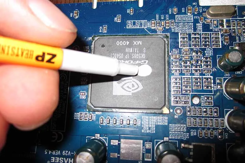
How you apply matters just as much as what you apply. The goal? Smooth coverage without overflow or dry spots.Pea-Sized Dot Method – This classic works well on most CPUs. Just one small blob in the center spreads under pressure.
- Line Spread – For rectangular dies like some Intel chips, a short thin line across the middle ensures better edge-to-edge contact.
- Cross Pattern – For large CPUs like Threadripper, an X-pattern helps reach all corners when compressed by the heatsink.
Now here’s where folks mess up:
- Using too much product—it oozes out and insulates instead of cooling.
- Spreading manually with cards or fingers—it introduces air bubbles.
- Reusing old paste—just don’t; it dries out and cracks over time.
Whether you're using high-viscosity metal-based pastes or silicone hybrids, keeping application minimal but effective ensures optimal performance from your cooler setup.
Ensuring Proper Adhesion: Techniques for Better Thermal Conductivity
Good adhesion means no trapped air—and that means better cooling when things get hot under pressure.
Apply consistent downward pressure during installation so that the heatsink squishes the paste evenly across every millimeter of surface area. Don’t twist it around once it makes contact—that just drags air back in.
Make sure mounting screws are tightened diagonally in alternating corners to balance force evenly across the chip surface—tightening one side too early can lift another side slightly, creating micro gaps invisible to the eye but deadly to thermal transfer efficiency.
In short? You don’t need fancy tools—just patience, steady hands, and even torque on those screws will do more than any expensive compound alone ever could when comparing results in real-world tests between thermal pads vs thermal paste solutions used improperly versus properly applied ones.
Final Thoughts on Thermal Pads vs Thermal Paste
Summary of Thermal Pads vs Paste: Which One Fits Your Needs?
Choosing between thermal pads and thermal paste depends heavily on your setup, budget, and performance needs. Here's a quick comparison to help you sort it out:
Material Type & Application
- Thermal paste offers superior heat transfer but requires careful application, especially over CPUs or GPUs.
- Thermal pads are easier to install and great for filling uneven gaps between components.
Performance & Conductivity
- Paste generally provides better conductivity, ideal for high-performance builds.
- Pads sacrifice some efficiency but offer solid baseline cooling with less mess.
Longevity & Maintenance
- Pads can be reused if handled properly; paste often needs reapplying after long-term use due to degradation.
Use Case Scenarios
| Production Scenario | Recommended TIM | Rationale | Key Specification |
| AI Server GPU Modules (>5K units/month) | Thermal Pad | Controlled BLT; SMT-compatible; no dispense variability | 8–15 W/m·K; 0.5–2.0 mm; dielectric >10 kV/mm |
| Automotive ECU / ADAS (high reliability) | Thermal Pad | No pump-out under thermal cycling; AEC-Q200 qualification path | 5–10 W/m·K; compression set <10% per ASTM D395 |
| Prototype / Low-Volume (<500 units) | Thermal Paste | Lower upfront cost; no die-cut tooling; manual application acceptable | 3–6 W/m·K; non-conductive formulation preferred |
| High-Power IGBT/ MOSFET Modules | Thermal Paste | Ultra-thin BLT (<50 μm) maximizes heat transfer under high clamping pressure | >5 W/m·K; metal-filled; >200°C rated |
| Field-Replaceable Assemblies | Thermal Pad | Clean removal; no solvent; consistent replacement performance | Non-adhesive; 5–8 W/m·K; Shore OO 30–50 |
| Optical / Cleanroom Electronics | Thermal Pad (Non-Silicone) | Zero siloxane outgassing; <0.05% TML per ASTM E595 | Non-silicone formulation; 3–8 W/m·K; UL 94 V-0 |
→ Discuss Your Application with a Sheen Technology TIM Specialist
Key Takeaways: Making the Right Decision for Your Cooling Requirements
There’s no one-size-fits-all when it comes to choosing between these two thermal interface materials. What matters most is matching the right product with your expectations and skill level.
- For beginners? Stick with thermal pads—they’re forgiving during installation and provide reliable insulation without fuss.
- For enthusiasts pushing clock speeds? Go for thermal paste—it delivers tighter contact points and better overall heat dissipation.
- For long-term stability? Look at specs like viscosity, curing time, and how frequently you'll need reapplication. If you want plug-and-play simplicity, grab a pad. If you're chasing peak efficiency down to the decimal point, get that tube of paste ready. Either way, understanding what each does best gives you control over your system's cooling game.
FAQs about Thermal Pads vs Thermal Paste
What determines the better choice between thermal pads and thermal paste in large-scale production?
A subtle tradeoff of precision and simplicity defines it.
- Thermal Conductivity Performance: Conductive Silicone Paste offers stronger transfer efficiency for CPU Heat Dissipation or GPU Thermal Management.
- Thermal Resistance Characteristics: Pads hold higher resistance but provide consistent placement across Power Electronic Components.
- Electrical Insulation Capability: Pads safeguard Integrated Circuit Packaging during Reflow Soldering Oven operation where insulation is vital.
In short, paste drives heat flow speed; pads deliver even, secure coverage.
How does automated equipment influence factory-wide material application?
Digital machines breathe rhythm into volume work—maintaining quality under pressure:
- The Automated Dispensing System ensures uniform feeding of Heat Conductive Compound along complex chip arrays.
- Screen Printing Equipment spreads the Phase Change Material swiftly across Printed Circuit Board Assembly lines with controlled thickness tolerance.
- Combined with a strict Quality Control Inspection, they minimize waste while maintaining adherence to IPC Standard Conformity standards.
Why do industrial designers often prioritize pastes inside performance-driven systems?
Inside power-hungry engines like High-Frequency Microprocessors and amplifiers:
★ Pastes adapt flexibly over uneven metal surfaces through Adhesion Promotion Techniques without extra machining work.
★ Their natural flow fills microscopic gaps under Power Amplifier Cooling needs before entering a Material Curing Schedule cycle monitored by temperature sensors.
This fluid contact yields powerful synergy between surface finish and Long-Term Stability Reliability ratings.
Which international standards define acceptable materials for mass order use?
The global supply chain translates safety into exact codes:
| Standard | Focus Area | Example Implementation |
| RoHS Compliance Certification | Restricts hazardous elements | Used during LED Thermal Conductivity module approval |
| REACH Regulation Adherence | Governs chemical properties | Guides Conductive Silicone Paste imports into EU |
| UL Flammability Rating | Fire safety threshold control | Applied on pad-based insulation layers over IC Package Heat Transfer zones |
Each certification solidifies trust—ensuring every Thermal Interface Material performs safely inside demanding electrical environments worldwide.
Sheen Thermal
Dongguan Sheen Electronic Technology Co., Ltd · Founded in 2008
Manufacturer of thermal interface materials and silicone foam for automotive electronics, energy storage, power electronics, communications and consumer electronics.
Certified
- ISO 9001:2015
- ISO 14001:2015
- IATF 16949:2016
What we supply
- Thermal conductivity Up to 90 W/m·K
- Thickness 0.3–10.0 mm
- Custom & samples Die-cut to drawing, 3–7 days